FINAL INDEPENDENT PROJECT
SURFACING AND SOLID MODELLING OF SHELBY GT-500 CAR
Objective:
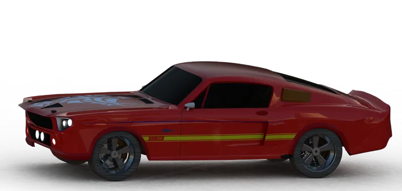
The primary target of this venture to make a virtual model of the SHELBY GT-500 vehicle utilizing SolidWorks 2021. In this task, the singular pieces of the car like primary body, seat, dashboard, entryway, controlling wheel, and sub-gatherings, for example, wheels and back tires get together are planned utilizing either surfacing or strong demonstrating. At last, reasonable perspectives are made utilizing photoview360.
Introduction:
A car is a wheeled motor vehicle used for transportation. Cars came into global use during the 20th century, and developed economies depend on them. The Shelby Mustang is a high-performance variant of the Ford Mustang built by Shelby American from 1965 to 1967 and by the Ford Motor Company. The production of the SHELBY GT-500 Sportroof was limited to a total of 1537 units.
Specifications:
Length: 1300 mm
Width: 482 mm
Height: 305 mm
Front tire: 187 mm
Rear tire: 185mm
SolidWorks –
The designing software allows the engineers to create the virtual models before a product is produced, and it also allows for much better visual representation of the product before manufacturing. It also helps engineers with various analysis to know whether product is ready for manufacturing or not. SolidWorks is a 3D CAD design software, analysis software and product data management software developed by Dassault systems. This software enables the designers and research engineers to model the products better, faster and more cost-effective.
Features of SolidWorks used in this project: -
Sketch tools -
Sketch Picture - Insert an image file into the background of a sketch. This allows the user to 2D sketches based off of the image. Use the sketch picture property manager to alter the inserted image.
Line - Line is one of the first sketching tools in Solid works Sketch Command Manager which can be drawn horizontally, vertically or at any angle. It plays very important role to complete the 2D drawing of the product or part and very easy to utilize its features.
Circle - The circle is another important sketching tool which enables to create the circular drawing on the graphics area.
Rectangle - Sketches rectangles or square with a centre point at a selected angle.
Spline - A 2D or 3D curves defined by a set of control points. Points within a spline can be added or deleted.
Sketch Fillet - A tangent arc in between two sketch entities can be created.
Convert Entities - Convert Entities enables you to copy model edges into your active sketch. These sketch elements are automatically fully defined and constrained with an On Edge relation. Convert Entities is like Offset Entities except that the offset distance is always zero.
Text - It can be used to write the text necessary wherever required either it's a plane or face.
Offset Entities - Copy a sketch entity to a specified distance from the original entity. Must have a sketch entity already drawn and selected to use this tool.
Mirror entities — A mirror feature is a copy of a selected feature, mirrored about a plane or planar face. A mirror sketch entity is a copy of a selected sketch entity that is mirrored about a centreline.
Smart Dimension - Creates a dimension for a selected sketch entity.
Solid modelling tools - Surface modelling is a method of creating planar or non-planar complex geometry which has zero thickness. Zero thickness geometry is known as surface.
Extruded Boss/Base - An Extruded Boss/Base feature will allow us to take a 2D sketch and add thickness to it in the third dimension.
Extruded Cut - It's a tool to remove material by projecting a sketched section normal to the sketching plane.
Revolved Boss— Revolves a sketch or selected sketch contours around an axis to create a solid feature.
Swept Boss — It Sweeps a closed profile along an open or closed path to create a solid feature.
Split - Lines are used to divide model faces into two. Split lines are created like any other sketched feature.
Dome - It can add one or more domes to the selected planar or non-planar faces. The software calculates the distance using the radius of the arc as a basis for the dome.
Fillet - A fillet is an internal rounding of a corner or edge in a sketch, or an edge on a Solid.
Shell – A shell is a feature used in solid modelling to covert any solid model into a hollow or make that model thickness as per your requirement.
Mirror – A mirror feature is a copy of a selected feature, mirrored about a plane or planar face.
Reference plane — We can create planes in part or assembly documents. We can use planes to sketch, to create a section view of a model, for a neutral plane in a draft feature, and so on.
Project Curve - Select Bi-directional to create a projection that extends on both sides of the sketch. The curve can be used as a path for a sweep.
Surfacing tools -
Extruded Surfaces — Extrudes a sketch or selected sketch contours in one or two directions two create a surface feature
Swept Surfaces — It Sweeps a closed profile along an open or closed path to create a surface feature
Boundary Surfaces - The boundary surface feature lets us to create surfaces that can be tangent or curvature continuous in both directions
Lofted Surfaces — Creates a lofted surface between two or more profiles or sketches. Specify start and end constraints and add guide curves to control the path shape.
Filled Surfaces — Patches a surface within a boundary defined by edges, sketches, or curves. We can use constraint curves to fill surfaces and adjust resolution control to improve surface finish.
Offset Surface — This tool helps us to create an offset surface with gaps.
Ruled Surfaces — Inserts ruled surfaces in a specified direction from edges. Tangent to surface, Normal to surface, tapered to vector, perpendicular to vector or sweep can be selected.
Fillet - A fillet is an internal rounding of a corner or edge in a sketch, or an edge on a surface.
Extend Surface — Extends one or more edges or faces on a surface, based on end conditions and extension type.
Projected curve — A projected curve is typically used either in sweeps and lofts as path or guide curve. There are two types of projected curves:
Sketch on Sketch: Use two sketches to make a single curve.
Sketch on surface: Use a sketch to project on a surface.
Trim Surface — It trims the surfaces where a surface intersects with another surface, a plane or a sketch
Knit Surface — It combines two or more adjacent, non-intersecting surfaces into a single surface body. The surfaces must joint at an edge. If the resulting knit surface encloses a volume, we can create a solid body from the Property Manager
Design Methodology:
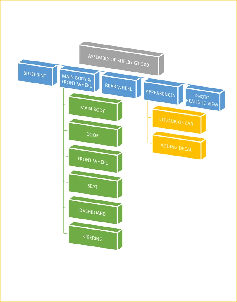
PART MODELLING DESCRIPTION:
- BLUE-PRINT SETUP: A blueprint is a reproduction of a technical drawing or engineering drawing using a contact print process on light sensitive sheets. A blueprint is a guide for making something, it's a design or pattern that can be followed. They were easier to read and faster to make.
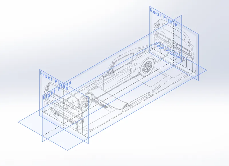
- The above shown Blueprint was used to model the SHELBY GT-500` in a fully defined constraint. For setting up the Blueprint the Sketch pictures options were used and placed the different blueprints at the required planes.
PARTS MODELLED:
- Main Body Assembly
- Main Body
- Seat x2
- Door x2
- Dashboard
- Steering
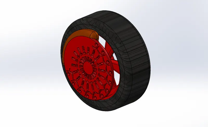
- Front Wheel
- Rear Wheel
- MAIN BODY ASSEMBLY:
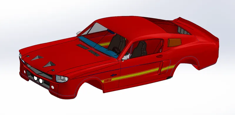
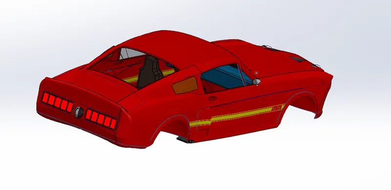
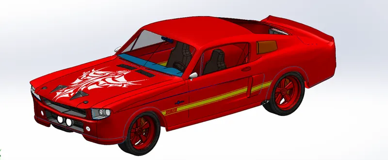
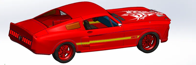
- The main body assembly consists of the main body of the car, doors, seats and dashboard. The main houses the all the components of the car including the chassis and frame.
- The main body of the car is created using the surfacing tools. Different curves are generated using the projecting the sketches which are drawn in reference to the blueprint. Most commonly surface loft, filled surface and trim surface tools are used.
- The main features used to create the main body of the SHELBY GT-500 are curve projection, surface loft, filled surface, extrude surface, sweep surface, trim surface, ruled surface, knit surface, etc.
Main body:
Wheel:
Assembly:
Rendering:
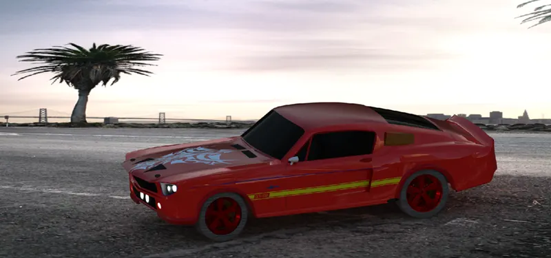
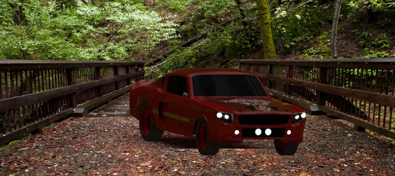
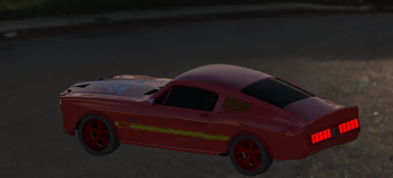
The photo realistic renders are created in SolidWorks using the add-in called PhotoView 360. The rendering of the image includes setting up the environment, arranging the lights, setting up the scenes and creating the final view of the designed part. SolidWorks visualize is also an add-in which is used to create the high quality rendered images with minimum amount of time.
CONCLUSION:
The project gave me a good understanding of how to convert a 2D blueprint into a nice 3D model. The surfacing and solid modelling are completely done in SolidWorks 2021. I got a good understanding of the surfacing modelling and learned about how to create the complex curves using project curves tools. In assembly, I learned about using the advanced and mechanical mates. Applying different background scenes, lights and setting up cameras in PhotoView 360 to create a good rendered view.