FINAL INDEPENDENT PROJECT
MBD I. Radial Engine
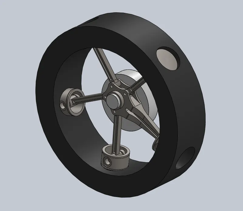
The Radial Engine is a reciprocating type internal combustion
engine configuration in which the cylinders point outward from
a central crankshaft like the spokes on a wheel.
This type of engine was commonly used in most of the aircrafts
before they started using turbine engines.
In a Radial Engine, the pistons are connected to the crankshaft
with a master-and-articulating-rod assembly. One of the pistons
has a master rod with a direct attachment to the crankshaft.
The remaining pistons pin their connecting rods` attachments to
rings around the edge of the master rod. Four-stroke radials
always have an odd number of cylinders per row, so that a
consistent every-other-piston firing order can be maintained,
providing smooth operation. This is achieved by the engine
taking two revolutions of the crankshaft to complete the four
strokes. Which means the firing order for a 9-cylinder radial
engine is 1,3,5,7,9,2,4,6,8 and then again back to cylinder
number 1.This means that there is always a two-piston gap
between the piston on its power stroke and the next piston on
fire(the piston on compression). If an even number of cylinders
was used the firing order would be something similar to
1,3,5,7,9,2,4,6,8,10 which leaves a three-piston gap between
firing pistons on the first crank shaft revolution, and only onepiston gap on the second crankshaft revolution. This leads to an
uneven firing order within the engine, and is not ideal.
6
The Four-stroke consequence of every engine is:
a) Intake
b) Compression
c) Power
d) Exhaust
Most radial engines use overhead poppet valves driven by
pushrods and lifters on a cam plate which is concentric with the
crankshaft, with a few smaller radials. A few engines utilize
sleeve valves instead.
7
II. History of the Radial Engine
The very first design of internal combustion aero engine made
was that of Charles Manly, who built a five-cylinder radial
engine in 1901 for use with Langley`s ‘aerodrome’ , as the latter
inventor decided to call what has since become known as the
aero-plane. Manly made a number of experiments, and finally
decided on radial design.
Radial Engine Characteristics
Rpm
Piston diameter Dp
Master-rod length Lmr
Crank Length Rcr
I. Kinematical and Dynamical Calculations
1. Ratio
Between the crank of the crankshaft and the master-rod length:
⋋=Rcr/Lmr
2. Angular velocity
Specifies the angular velocity of the object and the axes about
which the object is rotating.
 =兀.n/30
3. Current Piston Stroke
Reciprocating motion, used in reciprocating engines and other
mechanisms is back-and-forth motion. Each cycle of
reciprocation consists of two opposite motions, there is a
motion in one direction and then a motion back in the opposite
direction. Each of them is called a stroke.

4. Area of the piston head:
Fp=兀D2/4
5. Different forces acting on the master-rod:
- Gas Forces, Pg, N - Analytical calculation of the gas forces as a
function of the angle of rotation of the crankshaft
Is done according to the next formula:

Design Parts of Radial Engine
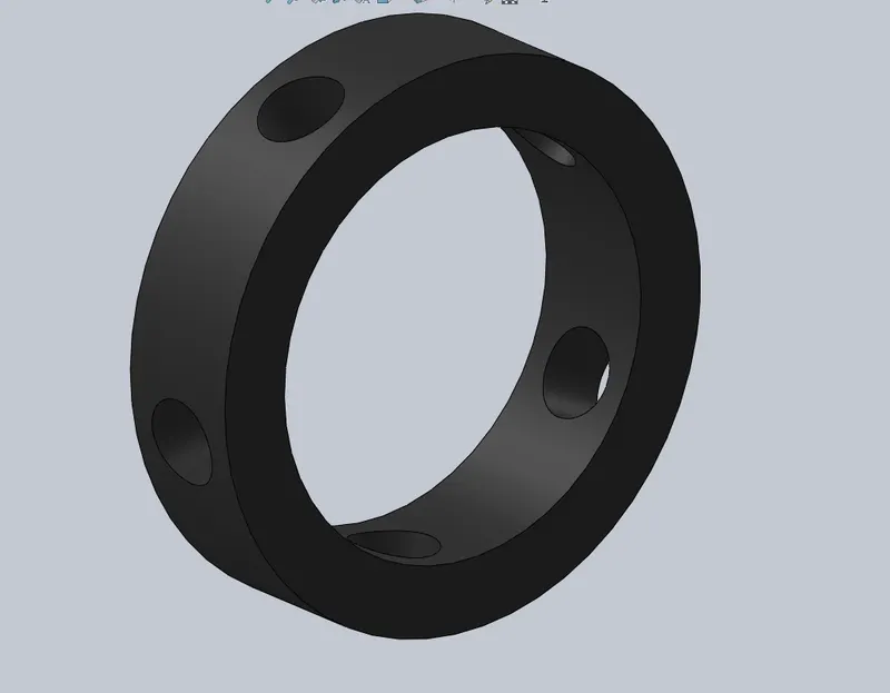
1.Ring
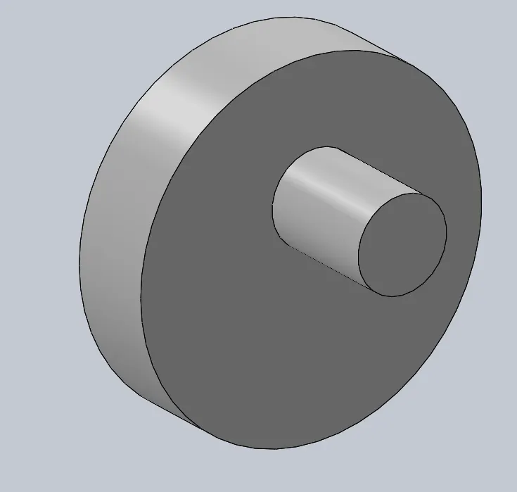
2. Crank
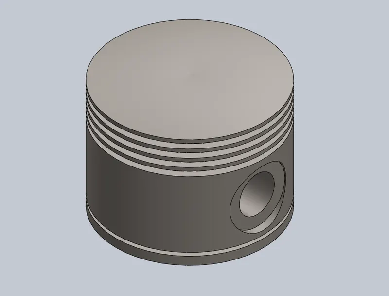
3.Piston
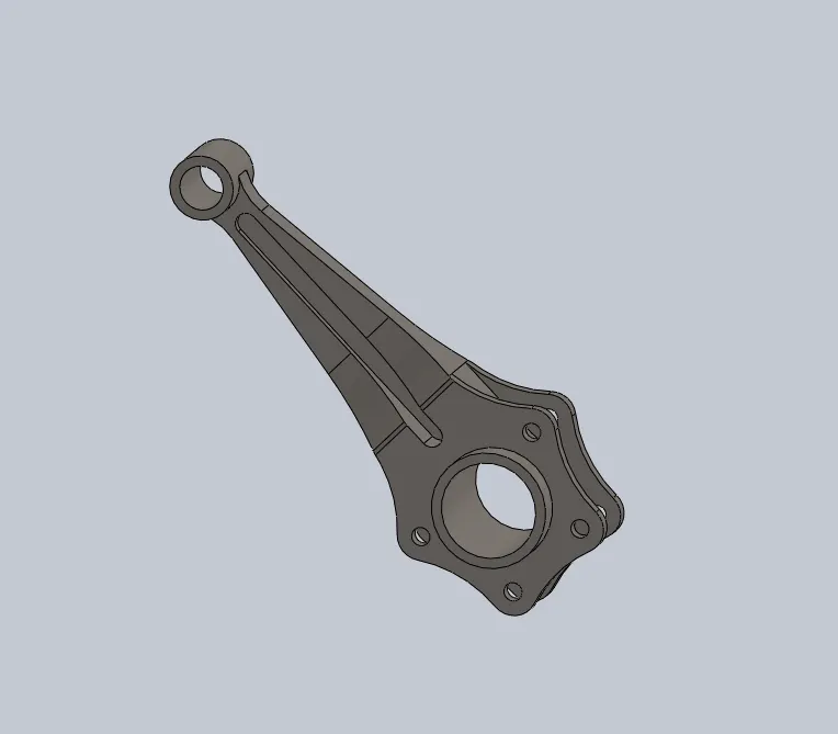
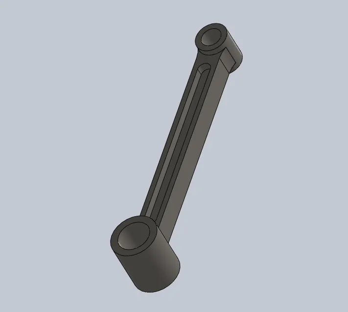
4. Master Connecting Rod
5. Auxiliary Rod
6. ASSEMBLY
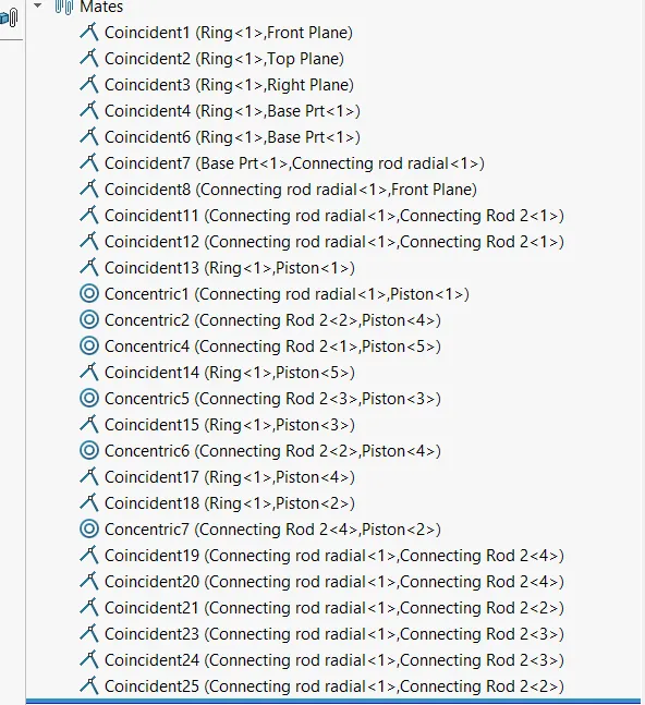
7. Mates
MBD ANALYSIS
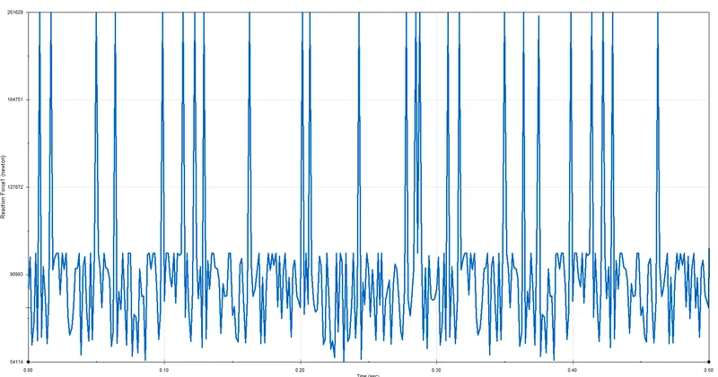
Contact Force
1. Crank and Master connecting rod
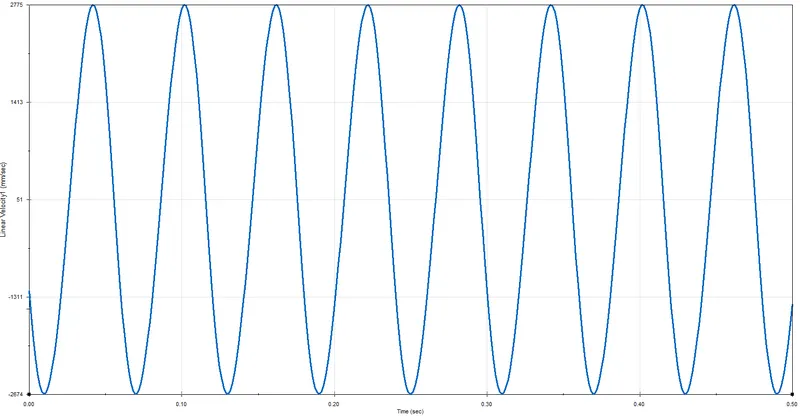
2.Linear Velocity of Piston
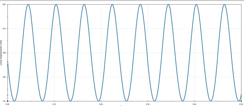
3.Linear Displacement of Piston
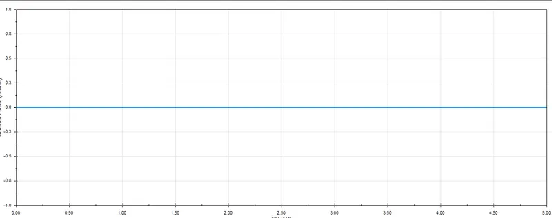
4. Contat Force betwwen Connecting Rod and Piston
Conclusion
1.we observe from the contact force btween crank and master connecting rod the variation in the contact force ,max force 201629 to min force 54114 and these variation showing a regular pattern .
2. Linear veloity of piston having a regular pattern as the piston moved fro and back . it attain the max to min value of 2774 to -2674 .
3. Linear displacement of piston also showing a regular pattern attain the value between 172 to 225 .
it show the total displacement 53mm covered by piston
4. contact force between connecting rod and piston is nuetral or can say a straight line .
Thus the MBD analysis is done on Radial Engine .