FINAL INDEPENDENT PROJECT
3D MODELLING, ASSEMBLY, AND PHOTOREALISTIC RENDERING OF WHEEL LOADER
OBJECTIVE:
- To model 15 individual parts of wheel loader with proper dimensioning and relevant features in Solidworks.
- To assemble all the parts using appropriate mates.
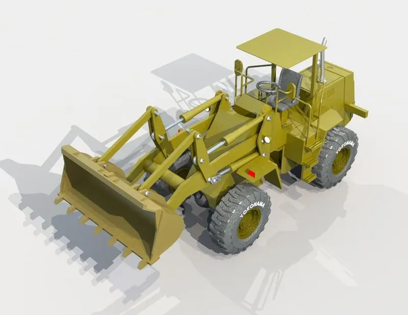
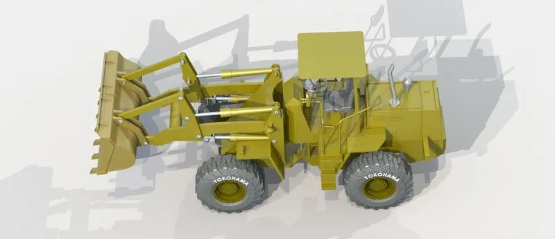
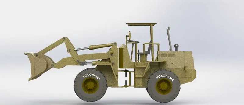
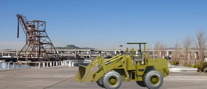
- Rendering final assembly to get photorealistic model using solidworks photoview 360 or solidworks visualise.
INTRODUCTION:
- Solidworks is a 3D CAD and CAE software developed by Dassault Systems. It provides dedicated tools and workflows that streamline the design and development of products. It is used for sketching, part modelling, sheet metal design, simulation, mold design, and other computer-aided manufacturing processes.
- Solidworks Visualize is a standalone computer application majorly employed to create photorealistic or non-photorealistic renders. It is also used for post-processing images and even creating basic presentation animations.
- Wheel loaders are a piece of heavy equipment usually found in construction projects and building sites. A wheel loader uses an arm to lift and lower its bucket, and a bell crank is used to open and close its bucket. Wheel loaders can lift almost anything such as debris, gravel, soil, dirt, pallets, etc.
DESIGN METHODOLOGY:
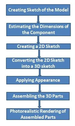
FEATURES AND TOOLS USED IN MODELLING OF WHEEL LOADER:
- Creating 2D Sketch - 2D Sketch is created on XY, XZ, or YZ planes. With the help of a 2D sketch, we create 3D features. The status of the sketch can be determined by color codes. If the sketch is black then it is fully defined, if the sketch is blue then it is under-defined, if the sketch is red then it is called over-defined.
- Extruded Boss/Bass - Using this feature we can create a solid which has the same boundary as that of the 2D sketch that we are using for extrusion.
- Knit Surface - Using this feature two or more than two surfaces can be joined and converted into a single entity.
- Trim Surface - Using this feature we can remove unnecessary surfaces.
- Extend Surface - Using this feature we can extend the surface using its edge.
- Fill Surface - Using this feature we can create the surface in the close boundary.
- Surface Extrude - Using this feature any 2D sketch can be extruded to create a surface.
- Revolved Boss/Bass - This feature is used to create a solid 3d model around an axis. With this feature, we can create cylindrical shapes.
- Swept Boss/Bass - Using this feature we can create complex hollow pipes, curved rods, tubes, twisted parts. Inputs for this feature are a path and sketch perpendicular to that path.
- Extruded Cut - Using this feature we remove solid which has the same boundaries as of that of the 2D sketch, this feature is used to create hollow surfaces.
- Lofted Boss/Bass - This feature is used to add materials between two or more profiles with ease. Inputs for this feature are cross-section and guide curve.
- Fillet - This feature is used to create smooth edges.
- Chamfer - This feature is used to create cuts (45-degree angle with the normal surface), or make edges or corners (vertex) of the 3D model straight.
- Circular Pattern - Using this feature we can create patterns of a feature, body, or face in a circular manner.
- Mirror - This feature is used to copy features across planes.
- Curve-driven Pattern -This feature is used to create patterns along a planar or 3D curve.
- Draft - We use this feature to provide taper on specified angles, using a neutral plane or parting line.
- Convert Entities - This feature is used to create a replica of a sketch entity or its dimensions in the same plane or another coordinate.
- Shell - This feature is used to create the spherical shape or Dome on 3D parts or shapes.
- Split - This feature is used to cut the part across some sketch boundary and to remove that part from the main model.
- Reference Geometry - This feature is used to create plans, axes, coordinate systems, and points.
- Projected Curves - This feature is used to create one 3D curve from two 2D curves drawn on different plans.
- Combine - This feature is used to join two or more solid bodies into a single entity.
COMPONENTS:
Wheel Loader consists of
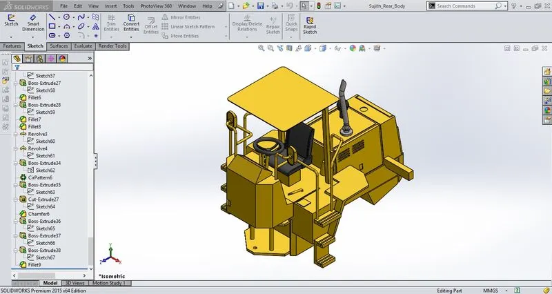
1. REAR BODY
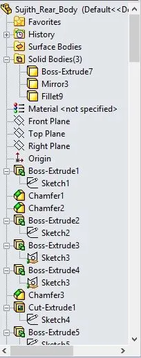
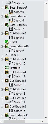
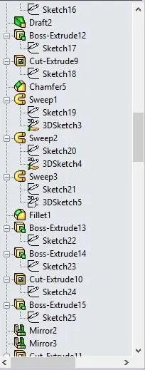
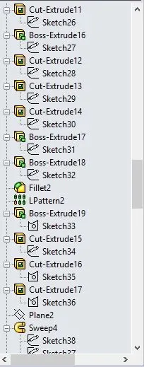
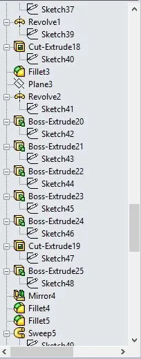
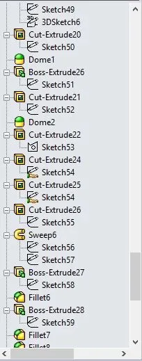
- Tools used to create rear body are Boss Extrude, Chamfer, Cut Extrude, Draft, Linear Pattern, Sweep, Fillet, Mirror, Revolve, Dome and Circular Pattern.
- Feature Tree and Isometric View
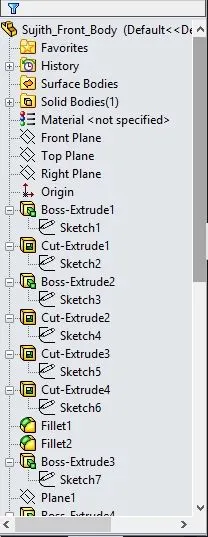
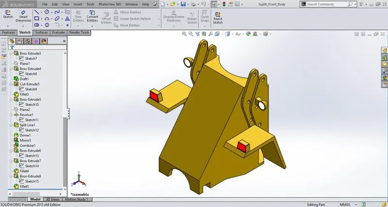
2. FRONT BODY
- Tools used to create front body are Boss Extrude, Cut Extrude, Draft, Fillet, Mirror, Dome, Revolve, Split Line and Combine.
- Feature Tree and Isometric View
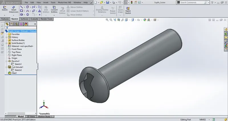
3. SCREW
- Tools used to create Screw are Revolve, Extrude Cut and Fillet.
- Feature Tree and Isometric View
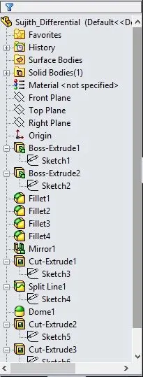
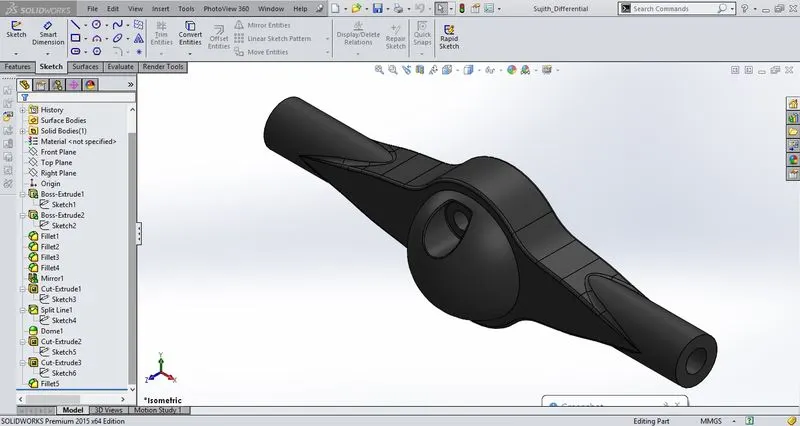
4. DIFFERENTIAL
- Tools used to create Differential are Boss Extrude, Fillet, Mirror, Cut Extrude, Split Line and Dome.
- Feature Tree and Isometric View
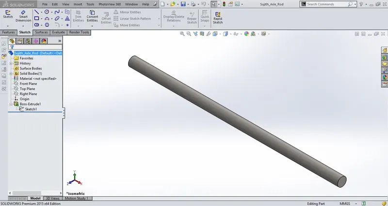
5. AXLE ROD
- Tools used to create Axle Rod is Boss Extrude.
- Feature Tree and Isometric View
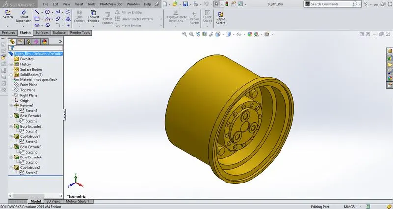
6. RIM
- Tools used to create Rim are Revolve, Boss Extrude and Cut Extrude.
- Feature Tree and Isometric View
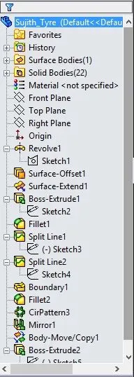
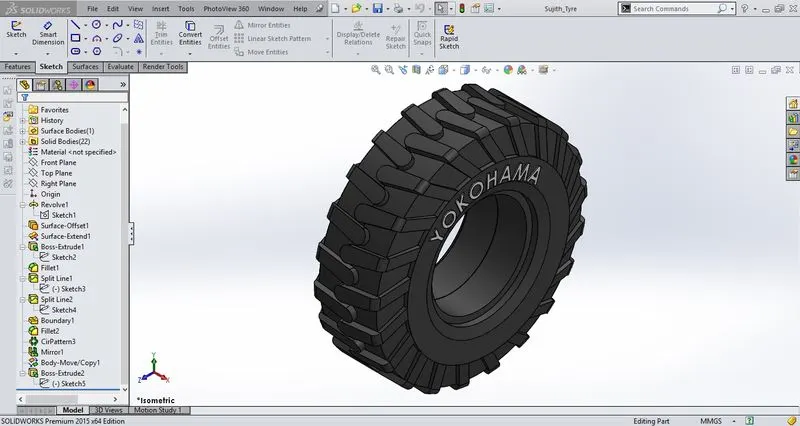
7. TYRE
- Tools used to Create Tyre are Revolve, Surface Offset, Surface Extend, Boss Extrude, Fillet, Split Line, Circular Pattern and Mirror.
- Feature Tree and Isometric View
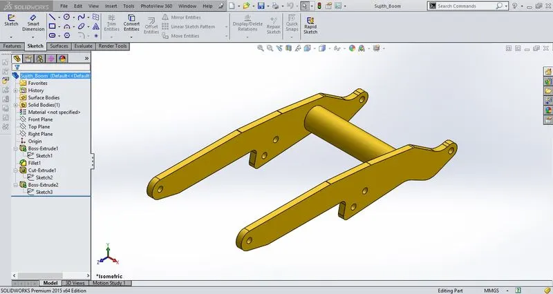
8. BOOM
- Tools used to create Boom are Boss Extrude, Cut Extrude and Fillet.
- Feature Tree and Isometric View
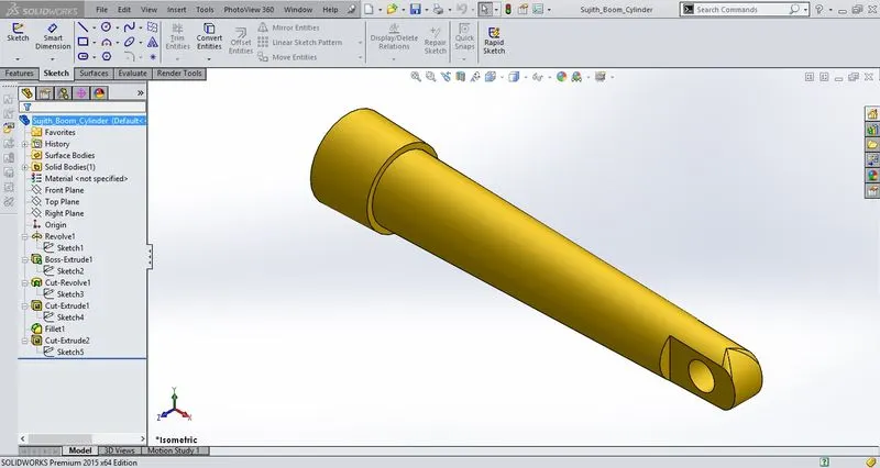
9. BOOM CYLINDER
- Tools used to create Boom Cylinder are Revolve, Boss Extrude, Cut Extrude and Fillet.
- Feature Tree and Isometric View
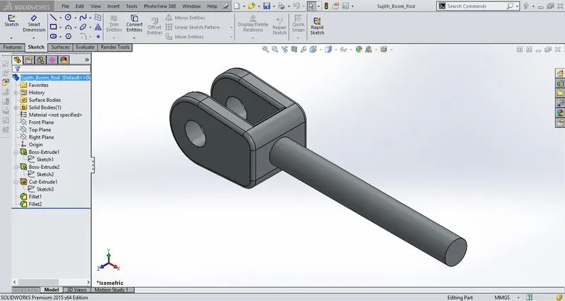
10. BOOM ROD
- Tools used to create Boom Rod are Boss Extrude, Cut Extrude and Fillet.
- Feature Tree and Isometric View
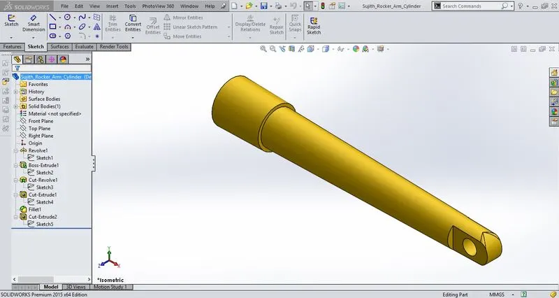
11. ROCKER ARM CYLINDER
- Tools used to create Rocker Arm Cylinder are Revolve, Boss Extrude, Cut Extrude and Fillet.
- Feature Tree and Isometric View
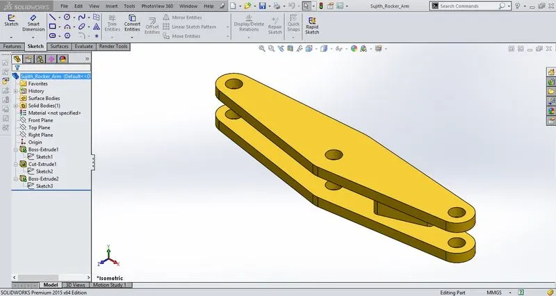
12. ROCKER ARM
- Tools used to create Rocker Arm are Boss Extrude and Cut Extrude .
- Feature Tree and Isometric View
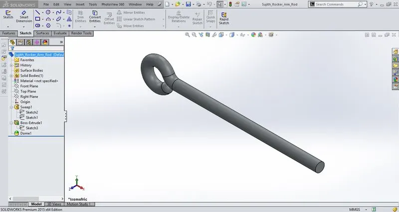
13. ROCKER ARM ROD
- Tools used to create Rocker Arm Rod are Sweep, Boss Extrude and Dome.
- Feature Tree and Isometric View
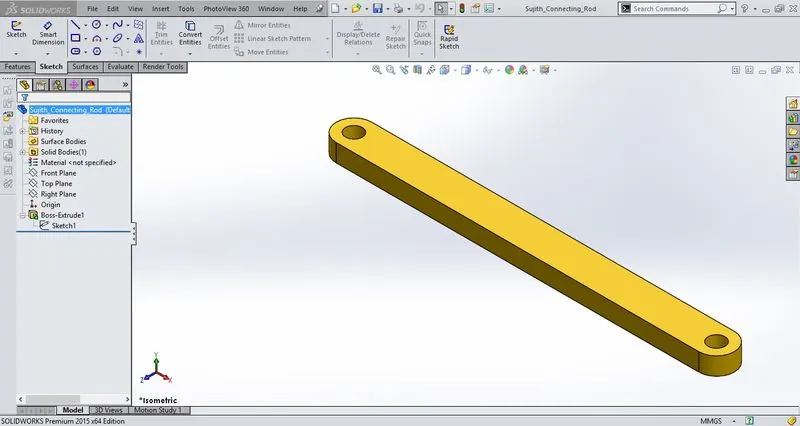
14. CONNECTING ROD
- Tools used to create Connecting Rod is Boss Extrude.
- Feature Tree and Isometric View
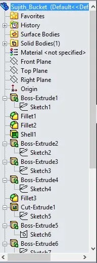
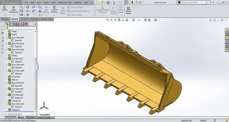
15. BUCKET
- Tools used to create Bucket are Boss Extrude, Fillet, Shell, Cut Extrude, Chamfer, Mirror and Linear Pattern.
- Feature Tree and Isometric View
ASSEMBLY:
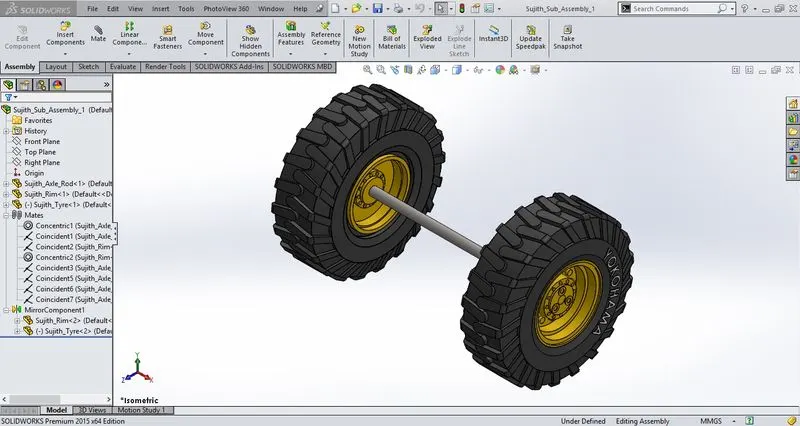
- SUB-ASSEMBLY - From the above mentioned components, Axle, Rim and Tyre were assembled earlier by using appropriate mates before the final assembly of wheel loader.
- In this Sub-Assembly after assembling the tyre and rim with the axle it is mirrored to get the below output.
- Feature Tree and Isometric View
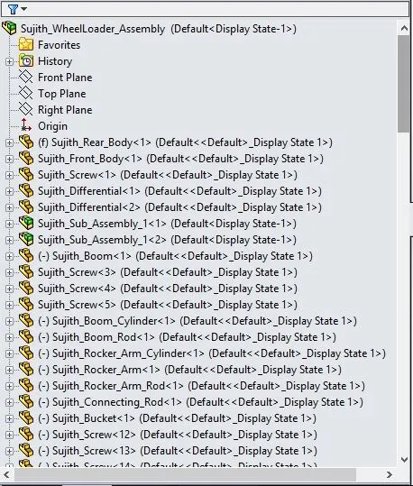
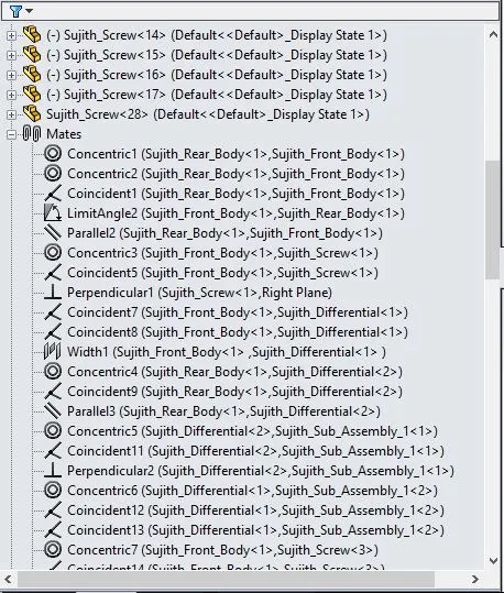
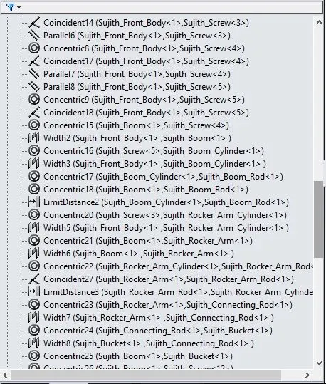
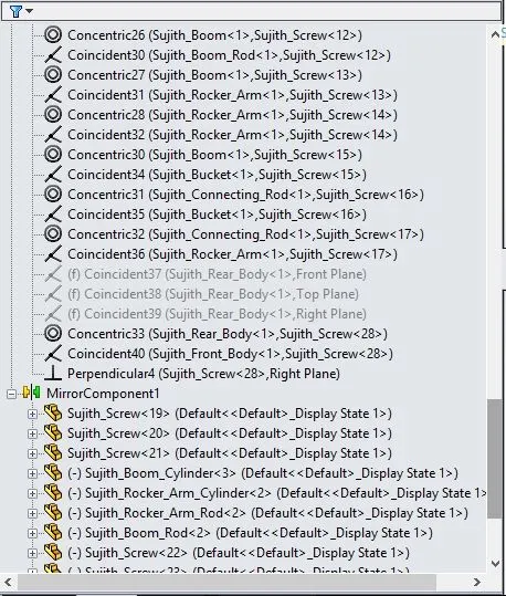
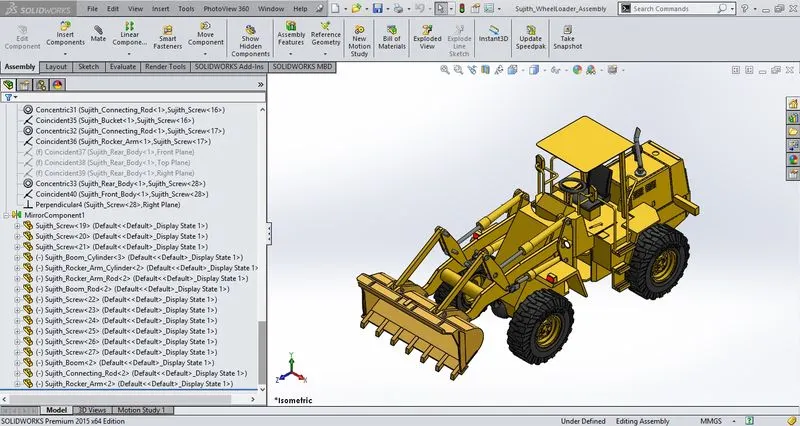
- Final Assembly - All components including the sub-assembly is assembled with appropriate mates to get the final wheel loader assembly.
- Total number of individual components used in the assembly is listed below.
-
COMPONENTS NUMBER FRONT BODY 1 REAR BODY 1 SCREW 20 DIFFERENTIAL 2 SUB-ASSEMBLY 2 BOOM 1 BOOM ROD 2 BOOM CYLINDER 2 ROCKER ARM 2 ROCKER ARM ROD 2 ROCKER ARM CYLINDER 2 CONNECTING ROD 2 BUCKET 1 - Feature Tree And Isometric View
- TOP AND BOTTOM VIEW
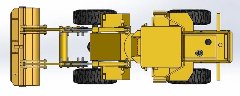
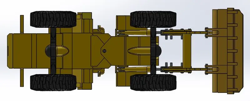
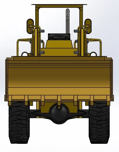
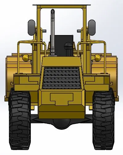
- FRONT AND BACK VIEW
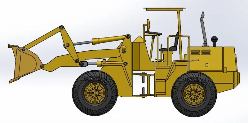
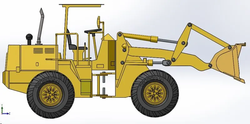
- LEFT AND RIGHT SIDE VIEW
RENDERED IMAGES:
CONCLUSION:
By this project i have learned-
- To design a part or a model with proper 2D sketching and dimensioning.
- To make a fully defined sketch,
- To model a part or component using different features like surface modelling and solid modelling etc..
- To make an assembly by using proper mates.
- To make a photo realistic view of a model by using photoview.360 and solidworks visualize.