FINAL INDEPENDENT PROJECT

OBJECTIVE:
- Designing a gazelle helicopter in solidworks2020 and rendering the model in solidworks visualization
- Assembling the swash plate mechanism on the model and to learn the working principle behind it.
INTRODUCTION:
- The Aérospatiale Gazelle is a French five-seat helicopter, commonly used for light transport, scouting and light attack duties. It is powered by a single Turbomeca engine and was the first helicopter to feature a fenestron tail instead of a conventional tail rotor. It was designed by Sud aviation, and manufactured in France.
- A lightweight observation helicopter intended to replace the Alouette III ; early on in the aircraft's development, the decision was taken to enlarge the helicopter to enable greater versatility and make it more attractive for the export market.
- Specification:
- Crew:1 or 2
- Capacity:up to 4 or 5 passengers
- Empty weight:917 kg (2,022 lb)
- Max take-off weight:1,800 kg (3,968 lb)
- Fuel capacity:735 l (194 US gal; 162 imp gal)
- Oil:13 l (3.4 US gal; 2.9 imp gal) for engine :3.5 l (0.92 US gal; 77 imp gal) for gearbox
- Power: 440 kW (590 hp)
- Maximum speed: 310 km/h (190 mph, 170 kn) at sea level
- Cruise speed: 264 km/h (164 mph, 143 kn) max cruise at sea level
- economical cruise speed: 233 km/h (145 mph; 126 kn)
- Range: 361 km (224 mi, 195 nmi) at sea level with maximum fuel
- Range with pilot and 500 kg (1,100 lb): 233 km (145 mi; 126 nmi)
- Rate of climb: 9 m/s (1,800 ft/min) max at sea level
HOW DOES A HELICOPTER WORKS?
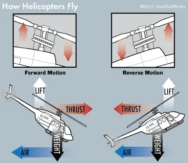
1) The science of a helicopter is exactly the same as the science of an airplane: it works by generating lift—an upward-pushing force that overcomes its weight and sweeps it into the air. Planes make lift with airfoils (wings that have a curved cross-section). As they shoot forwards, their wings change the pressure and direction of the oncoming air, forcing it down behind them and powering them up into the sky: a plane's engines speed it forward, while its wings fling it up.
2) Helicopters works on Bernoullis principle,Bernoulli's principle is an idea of fluid dynamics. It says that as speed of the fluid increases, pressure decreases.A higher pressure pushes (accelerates) fluid toward lower pressure. So any change in a fluid's speed must be matched by a change in pressure (force).
SWASH PLATE MECHANISM:
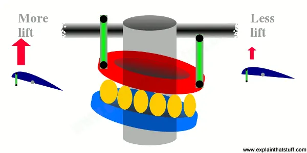
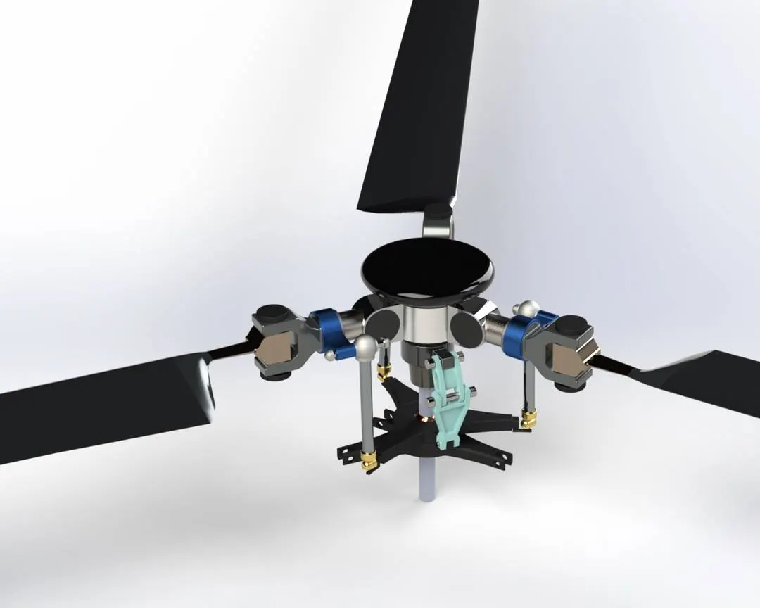
A swashplate is a device that translates input via the helicopter flight controls into motion of the main rotor blades. Because the main rotor blades are spinning, the swashplate is used to transmit three of the pilot's commands from the non-rotating fuselage to the rotating rotor hub and mainblades.
DESIGN APPROACH:
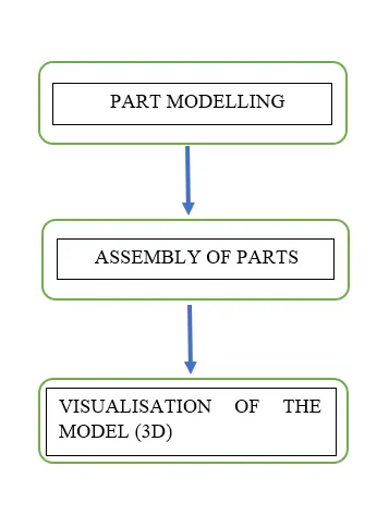
I applied a Bottom-Up assembly approach.
Design steps:
DESCRIPTION:
The Gazelle Helicopter consists of more than 1000 parts, But Here I designed the major parts they are,
- MAIN BODY
- ENGINE BODY COVER
- MAIN ROTOR (SWASH PLATE MECHANISM)
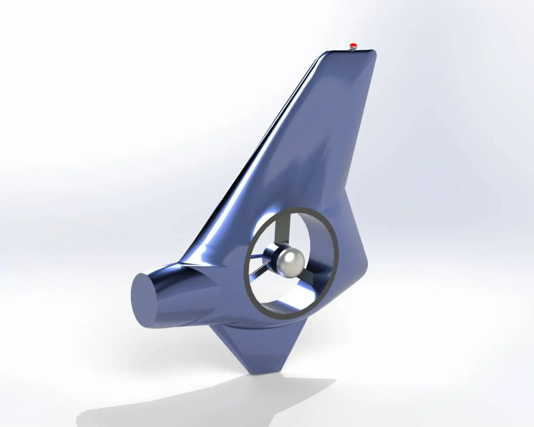
- TAIL ROTOR AND TAIL BODY
- DOORS
- PILOT CABIN
- LANDING SKIDS
FEATURES AND TOOLS USED:
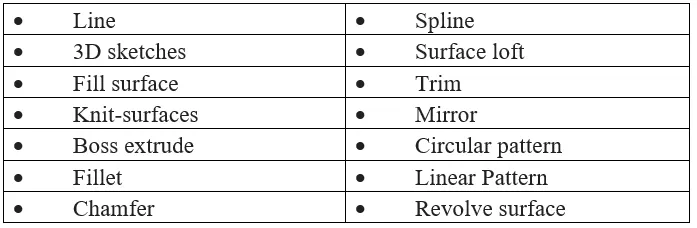
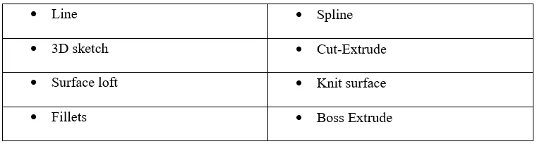
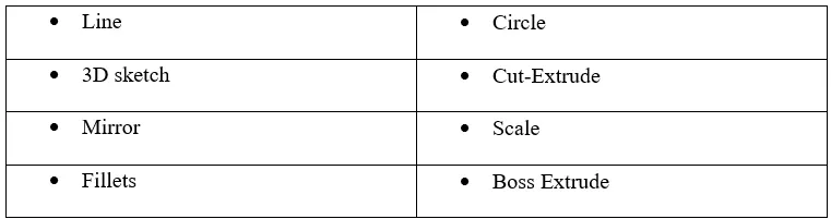
1) 2D-sketch: It is the basic tool to create geometry like circle,line,spline,rectangle,etc.
2) 3D-sketch: It is used to create a sketch on the 3D.
3) Boss/bass Extrude: It is used to add some thickness to the sketch or to convert 2D into 3D.
4) Revolve: This tool is used to create an extrude in an revolve(round) around the selected axis.
5) Trim: It is used to erase the unwanted entities on the sketches.
6) Extrude cut: It is used to cut the selected solid bodies in the model.
7) Reference plane: This feature provide a new datum plane which it allows to create a new sketch on the region.
8) Projection curve: This feature is to provide a curve where it requires two individual sketches,when these two sketches coincide eachother will provide the curve.
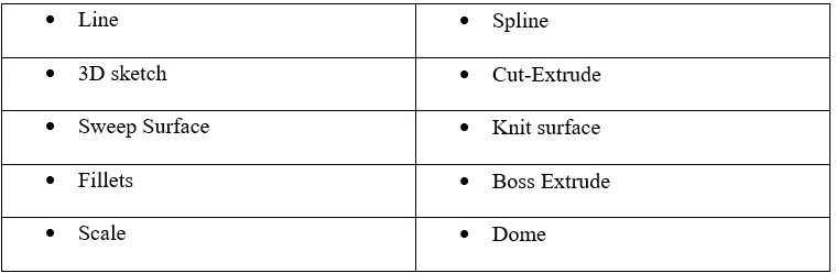
9) Loft surface: It is used to create a surface with reference taken from the sketch and it provides a surface along the sketch.
10) Fill-surface: This is used for fiiling the surface on the open region and it requiers a closed profile.
11) Knit-surface: It is used to join two or more individual surface into a single surface and can also be converted into solid body.
12) Linear pattern: This tool is for creating the same geometry of selected sketches into number of enities along with the path or direction.
13) Circular pattern: It is similar to the linear pattern instead of linear direction it will create the selected geometry in circular way.
14) Mirror entites: This feature is used create a copy or mirror of the sketch with reference to the centre axis.
15) Mirror: This is used to mirror the bodies or features with referenece to the plane.
16) Thicken: It is used to add some thickness to the surfaces.
17) Fillets: It is used to provide smooth region on the edges.
18) Chamfer: It is similar to fillet but here it provide bend with respect to angle and the length.
19) Scale: It is used to resize the model in aspects ratio.
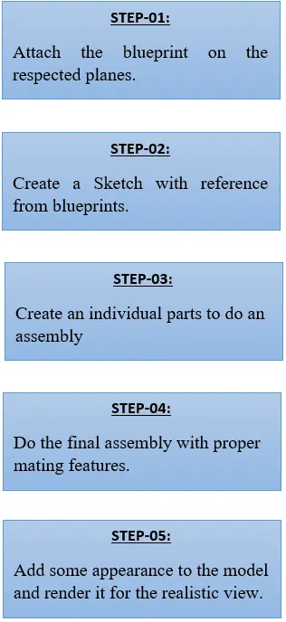
STEP-01:
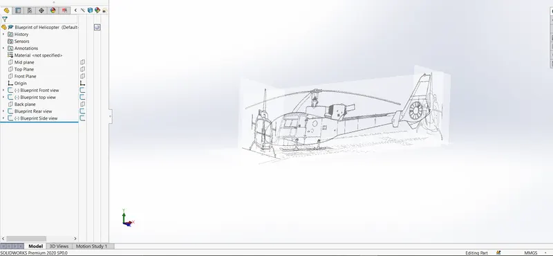
Open the solidworks window and attach the blueprints to the respective planes (Front plane,Top plane, Right plane,etc)
STEP-02:
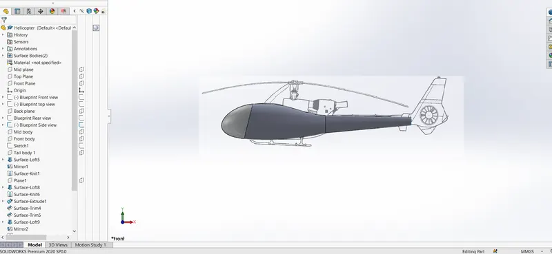
Create a 2D-sketch with respect to the blueprints attached,here the first part is to create the main body of a helicopter.
Features used:

STEP-03:
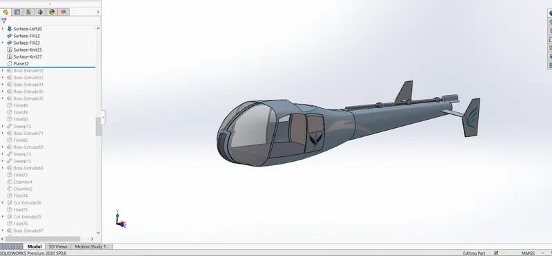
Create a 2D sketch for spliting the door component from the main body and provide the further cutouts and sketches .
Features Used:
STEP-04:
Create an Engine body cover in the helicopter main body.
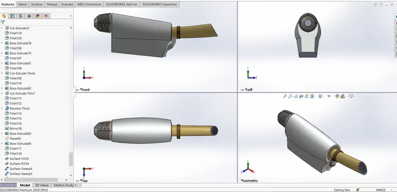
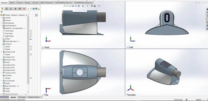
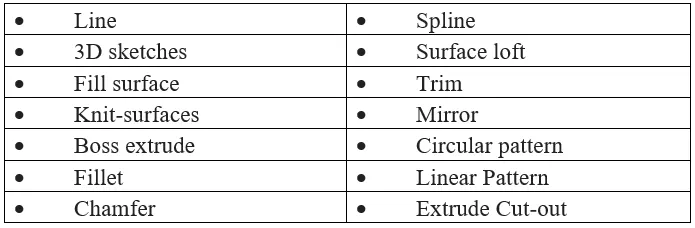
Features Used:
STEP-05:
Creating the Tail rotor and Tail Body,This tail parts are located Rear side of the helicopter and the tail rotor function is to control the
helicopter to move side ways (i.e Right and left sides).
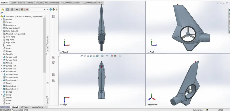
Features used:
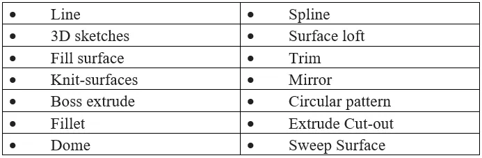
STEP-06:
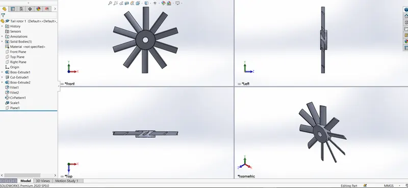
Creating a tail rotor it is used to rotate on an axis and helps the helicopter to move left and right sides.
Features Used:

STEP-07:
Creating a main rotor part,In this part we need to add some details to show as an mechanism,so there are sub parts used in this main rotors they are
- Upper Swash plate (Rotatable)
- Lower swash plate ( Fixed)
- Bearings
- Centre Ball
- Linkages
- Wing Blades
- Wing Holder
- Rotor must rod
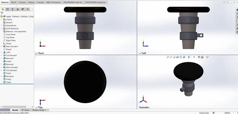
UPPER SWASH PLATE:
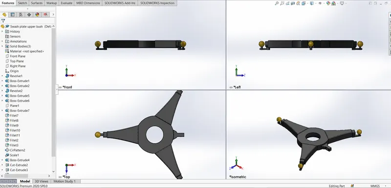
Features Used:
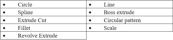
LOWER SWASH PLATE:
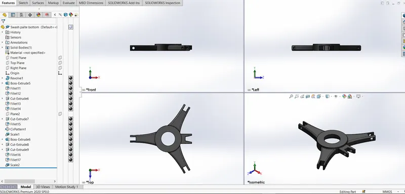
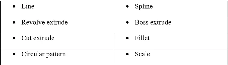
Features Used:
BEARINGS:
Bearings perform the function of preventing damage from being done by this force to the part that supports the rotation, and
also of maintaining the correct position of the rotating shaft.
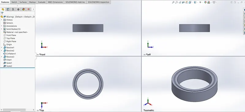
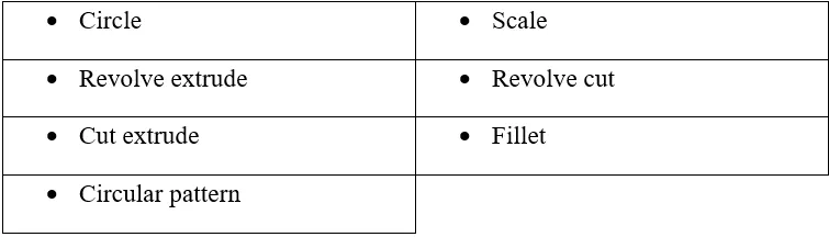
Features Used:
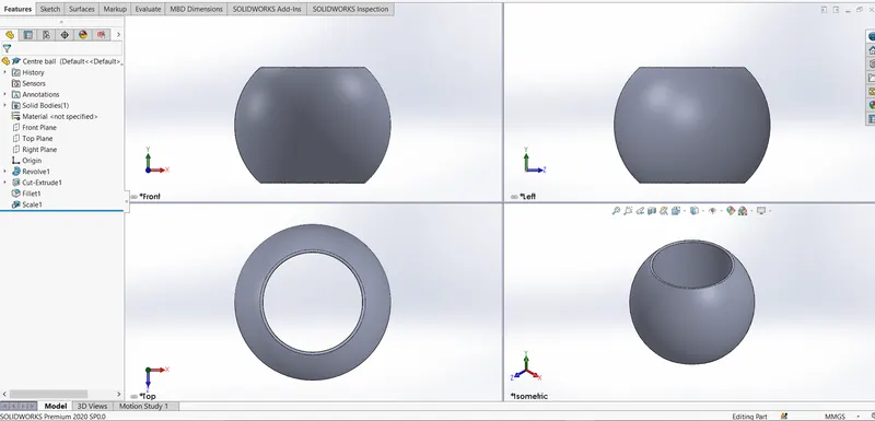
CENTRE BALL:
This centre ball is attached in b/w the swash plates and it will revolve on the axis.
Features Used:

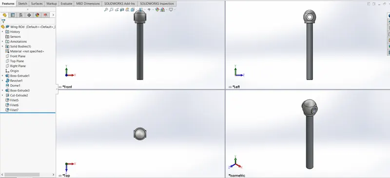
LINKAGES:
It acts as an linkage between the swash plates and the wing body.
Features Used:

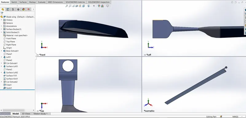
WING BLADES:
Creating a blades of the main rotor and it will be in airfoil shape.
Features used:
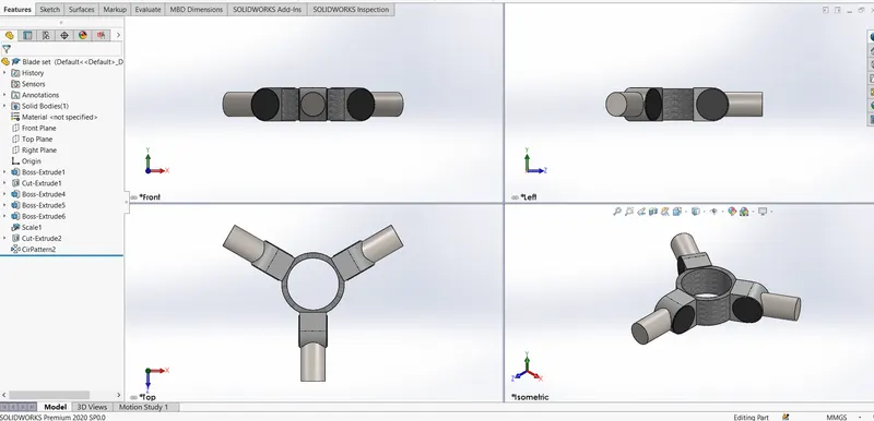
WING HOLDER:
It's Purpose is to hold the wing blade attached with the main shaft.
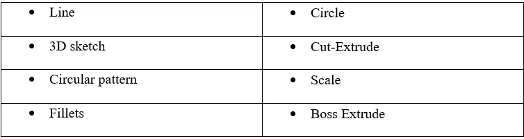
Features Used:
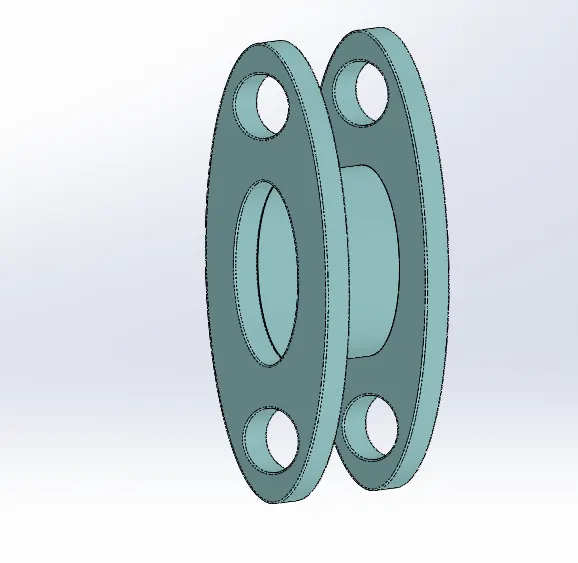
ROTOR MUST ROD:
It's function is used to control the pitch angle for taking off and landing the helicopter.
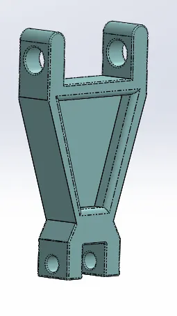
Features Used:
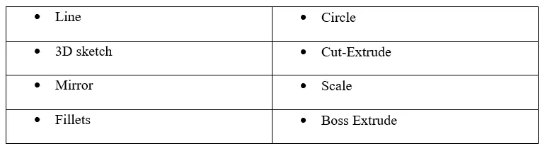
Bolt,Holder,etc:
This are the further components used to assemble the modeled parts.
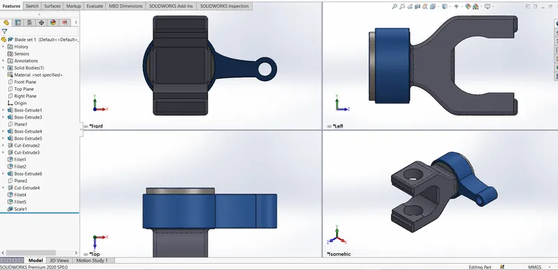
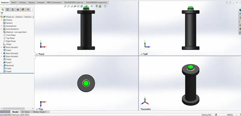
Features Used:
DOORS:
It is created by split body on the main body,Door acts as an protection for the pilots.
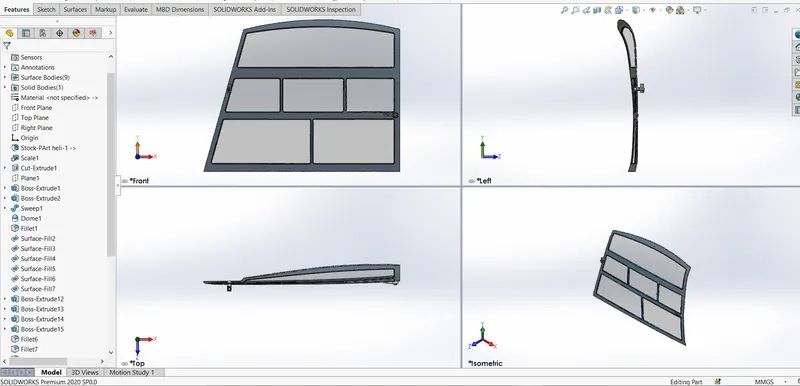
Features used:
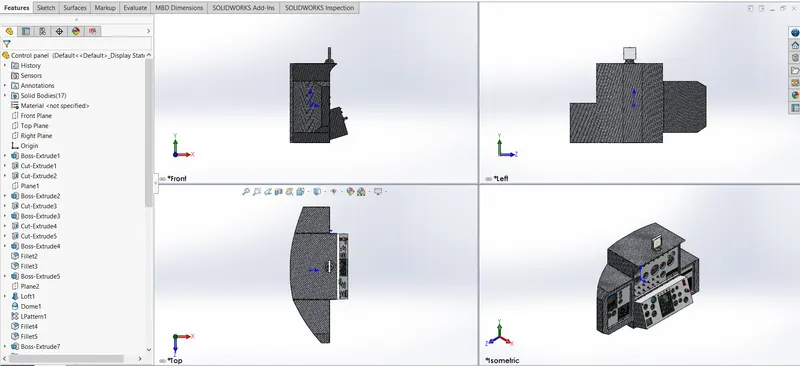
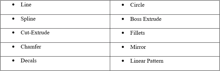
STEP-08:PILOT CABIN:
In this part we need to design the seats,controlpanel,joystick,pitot tube,etc
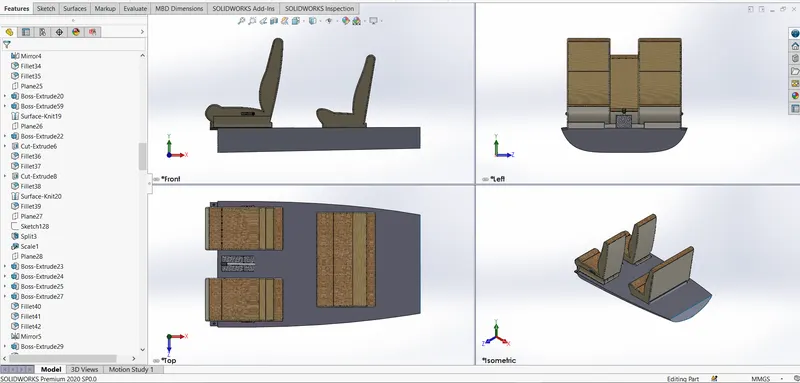
Features used:
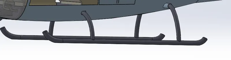
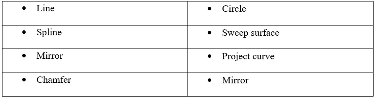
STEP-09:LANDING SKIDS:
It is used to land the helicopter on the flat surfaces it act as an stand.
Features Used:
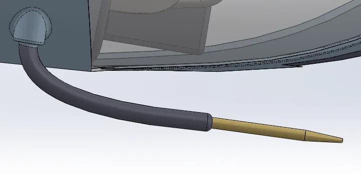
STEP-10:PITOT TUBE:
It is used to calculate the air speed and provide information on the panel and it as heater to avoid freezing while flying on high altitudes.
Features Used:
ASSEMBLY:
In this section we are going to assemble the individual parts in to a single body.
Here i have done two part assemblies.
- Main Rotor assembly
- Main body assembly
MAIN ROTOR ASSEMBLY:
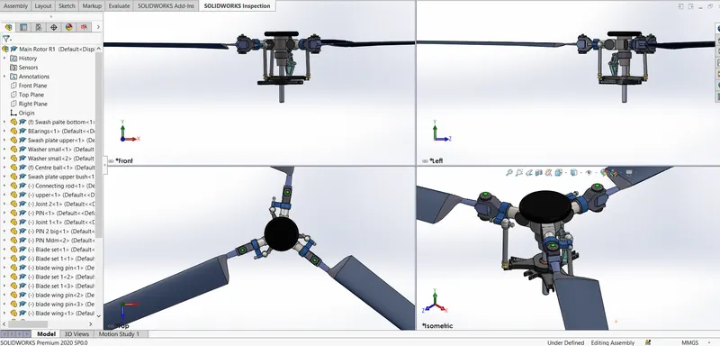
Assembling the sub parts of the main rotor into single body and mating to create a mechanism on it.
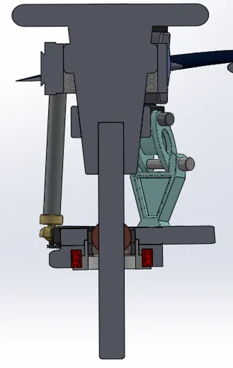
Cut-section:
Mate Conditions:
- Concentric
- Distance
- Coincident
- Angle
MAIN BODY ASSEMBLY:
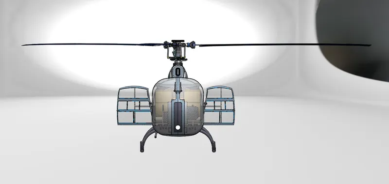
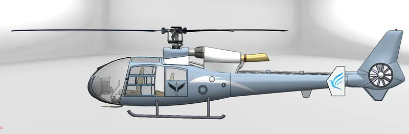
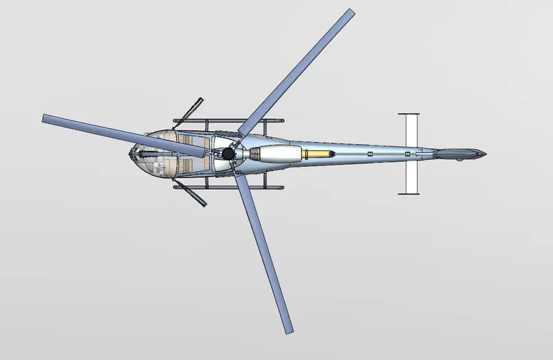
In this section all the parts are mated and full view of the helicopter is made with adding some decals to it.
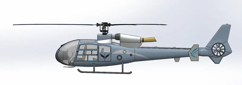
Mate conditions:
- Concentric
- parallel
- Coincident
- Distance
VIEWS:
Front View:
Side view:
Top view:
Rear view:
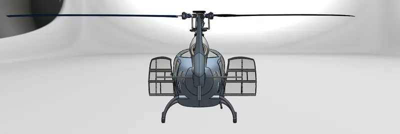
Isometric view:
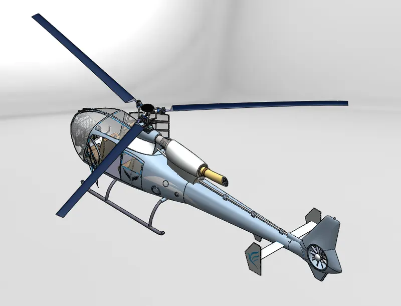
RENDERED IMAGES:
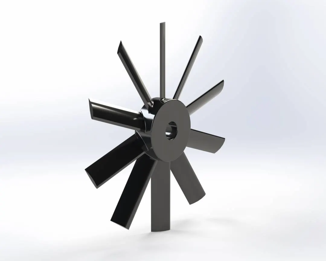
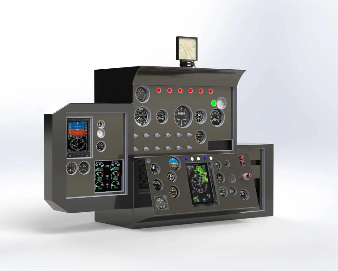
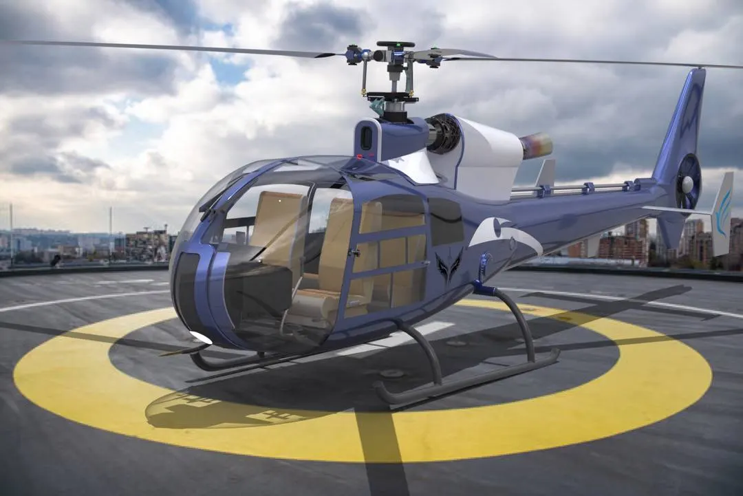
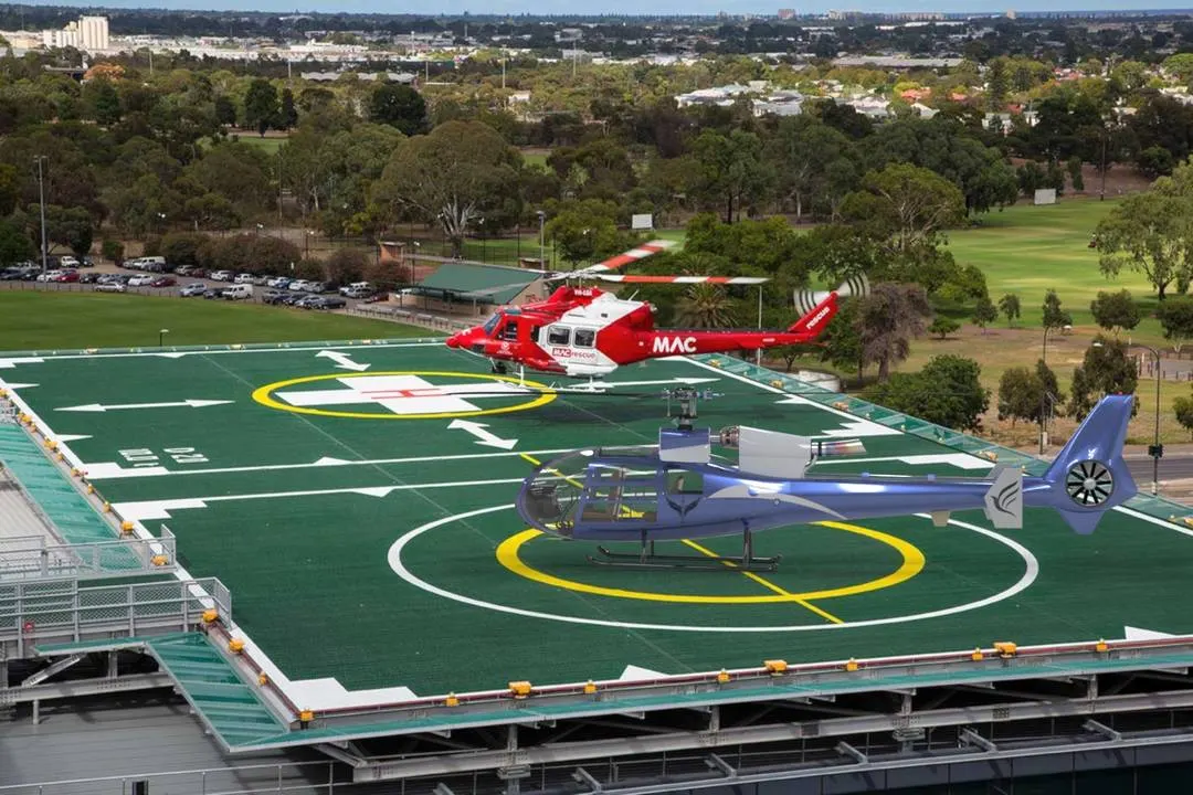
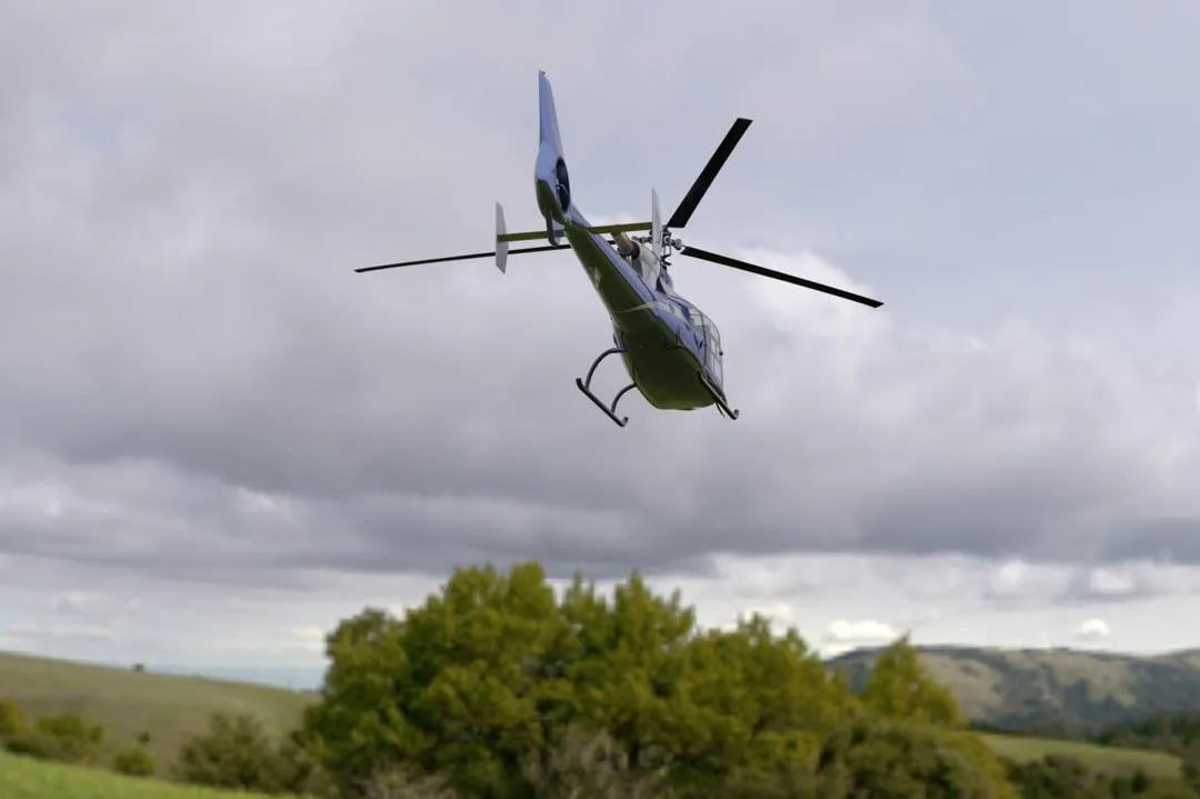
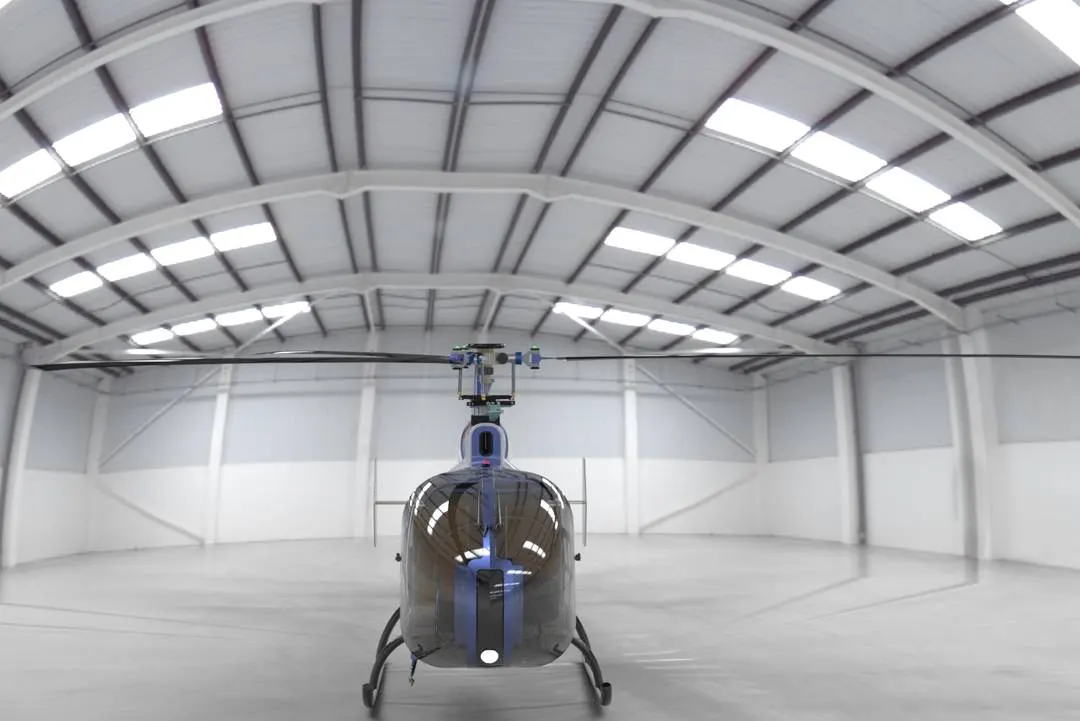
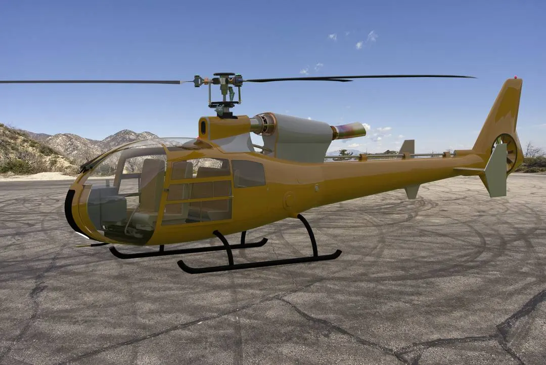
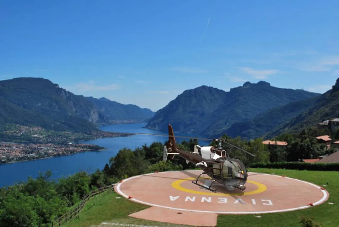
Different appearances given to the model on different environments by solidwork visualize.
CONCLUSION:
- Finally the Gazelle helicopter is designed and modeled in solidworks 2020
- The swatch plate mechanism is learned and designed
- The realestic view of the helicopter is achieved by solidworks visualize.
REFERENCES:
- https://fas.org/man/dod-101/sys/ac/row/gazelle.htm
- https://en.wikipedia.org/wiki/Swashplate
- https://www.nasa.gov/audience/forstudents/5-8/features/nasa-knows/what-is-a-helicopter-58.html
- https://www.youtube.com/watch?v=ZTvjzbdXd-M&list=LL&index=11
- https://en.wikipedia.org/wiki/Ducted_fan
- https://en.wikipedia.org/wiki/Fenestron
- https://www.airliners.net/aircraft-data/aerospatiale-alouette-iii/8
- https://www.explainthatstuff.com/helicopter.html