Fender Design - Wheel Arch Challenge
FENDER DESIGN - WHEEL ARCH CALCULATION:
AIM:
To Calculate the Wheel Arch gap at required points and check whether the car passes the European standard.
INTRODUCTION:
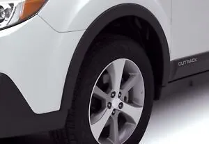
Fender is the part of automobile that frame of wheel well.Its primary purpose is to prevent the sand, mud, rock, liquid and other road spray from being thrown into the air by the rotation of tire. When the vehicle is moving tires pick up the stones and huel them to the all direction fender are basically present to prevent any injuries to pedestion and contain the motion of there particle.Most passenger automobiles have four fenders, one over each wheel. For vehicles with a narrow car body that exposes the tire, the fender is an exposed curve over the top of the tire. For wide body vehicles that cover the tire, the fender forms the wheel well surrounding the tire, and is not directly visible from above the car body.Wheel wells tend to be much larger than the diameter of the tire, because they do not move with the tire suspension and consequently must be large enough to allow the full range of tire motion on the suspension without touching the interior of the wheel well.More elaborate designs include fender skirts for enclosing the outside edge of the wheel well, and stylized pontoon fenders for exposed fenders.
WHEEL ARCH:
Wheel Arch is the semicircular curve on the fender just above the wheels of the carIt has some standard specificationsFor a vehicle to has its use permit in different countries, the wheel arch of the fender must compliant with the standards set by the respective countries.
WHEEL ARCH REGULATION :
JAPAN REGULATION:
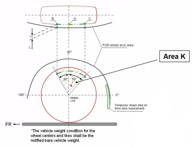
- The clearance ‘L’ for tire, hub, cap and fender is to be measured within area K and create clearance check chart to validate.
- The value of L should be greater than 5mm at all positions.
- Wheel guard requirement: The value of ‘a’ should be more than 5mm at line 30° forward and 50° rearwards from the central vertical axis of the wheel.
EUROPEAN REGULATION:
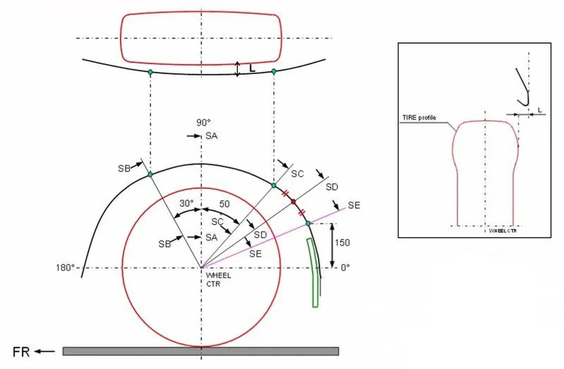
- The Clearance ‘L’ should be measured at sections SA-SA, SB-SB, SC-SC, SD-SD and SE-SE and create clearance check chart to validate.
- At all the five sections the value of L should be greater than 10mm to satisfy the European Regulations.
- Wheel guard requirement: The value of ‘a’ should be more than 5mm at line 30° forward and 50° rearwards from the central vertical axis of the wheel.
US REGULATION:
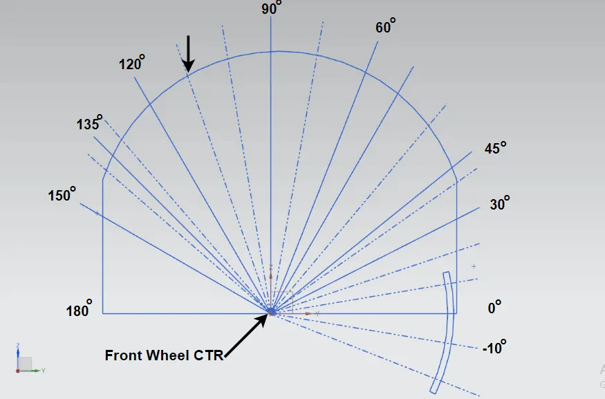
- Make clearance check details on all positions from -100* to 100* & make the clearance check table.
- All values should be greater than 5 mm to satisfy the regulations. The value of 'a' shall be more than 5 mm at a line 30* forward and 50*. Rearward from the central vertical axis of axis of wheel.
CALCULATION OF WHEEL ARCH AREA ACCORDING TO EUROPEAN REGULATION:
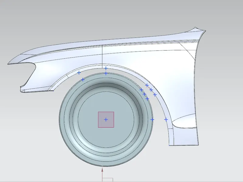
- To create datum plane at the referance of face at the wheel.
- And create a sketch at the referance of datum plane .
- Use project curve project the wheel arch and wheel .
- With use line command drawn line at the perpendicular of the mid point of the wheel curve.
- Then create the point at the intersection between wheel arch curve and line .
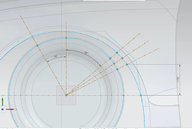
- A perpendicular line SA is dropped at the centre of the wheel
- Two lines SB and SC are created at 30° forward of SA and 50° rearward of SA respectively
- A point is created 150mm vertically above the centre line
- A line SE is drawn from the wheel centre and passes from the point created
- Another line SD is drawn from the centre of the wheel and in the middle of lines SC and SE.
CALCULATION TABLE:
| S.NO | SECTION | L<(10 | RESULT |
| 1 | SA-SA | 9.949mm | FAIL |
| 2 | SB-SB | 10mm | PASS |
| 3 | SC-SC | 0.1139mm | FAIL |
| 4 | SD-SD | 2.8875mm | FAIL |
| 5 | SE-SE | 5.9973mm | FAIL |
CONCLUSION:
From the above measurements it was observed that the clearance value 'L' at sections SA,SC,SD & SE was lower than 10mm and therefore it does not satisfy the European regulations. Whereas, the clearance value 'a' was more than 5mm at a line 30° forward and 50° rearward from the central vertical axis of wheel.