Fender Design - Wheel Arch Challenge
AIM To Calculate the Wheel Arch area and prove whether the car will pass the standards or Not.from the given fender as per the european standards.
DESCRIPTION wheel arch of fender acts as the protection of the car body of engine compartment & covers the wheel ,the main requirement of the fender is when the car is in motion the tier rotates & by the effect stones dust particals sand etc on the road will hit the body to restrict them not to allow inside of the engine commpart & also not to effect the pedestriants on the road. it is positioned to the bumper & a pillar (body of the car)
The main purpose of fenders is to prevent the dirt and debris kicked up by your wheels from damaging the sides of your car. The fender catches anything brought up by your wheels and causes it to drop straight down instead of spattering against or scratching your vehicle
The fender is the part of the car directly over the wheel well which helps prevent debris and grime kicked up by the wheels from damaging the sides of the car or other nearby vehicles while you drive. The fender also protects the wheels from side impacts and other potential damage
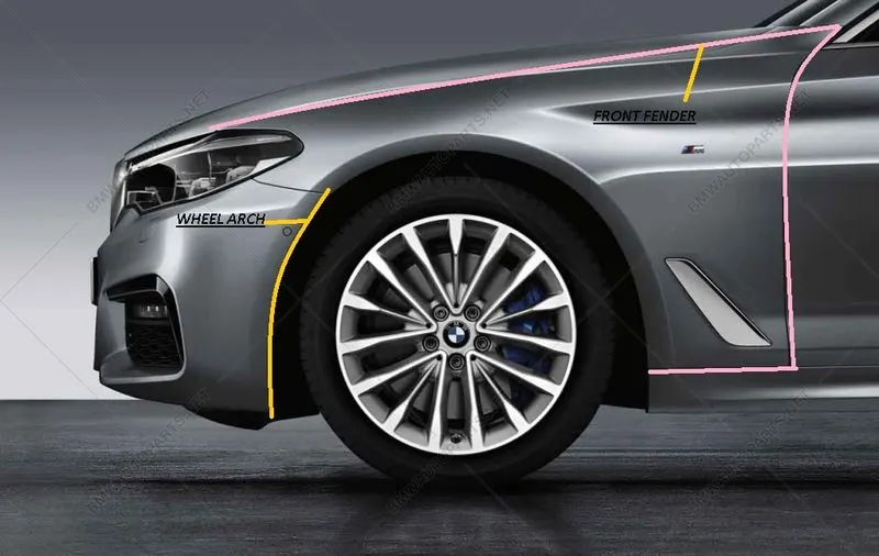
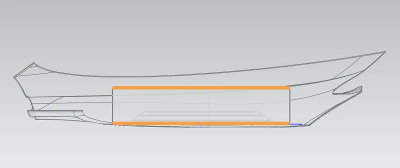
yellow coloured line is the wheel arch
pink colour line is fender (just for referance.)
As per the japan standards.
to satisfy the wheel arch radius should be 5mm between the tier & the fender edge.
US STANDARDS
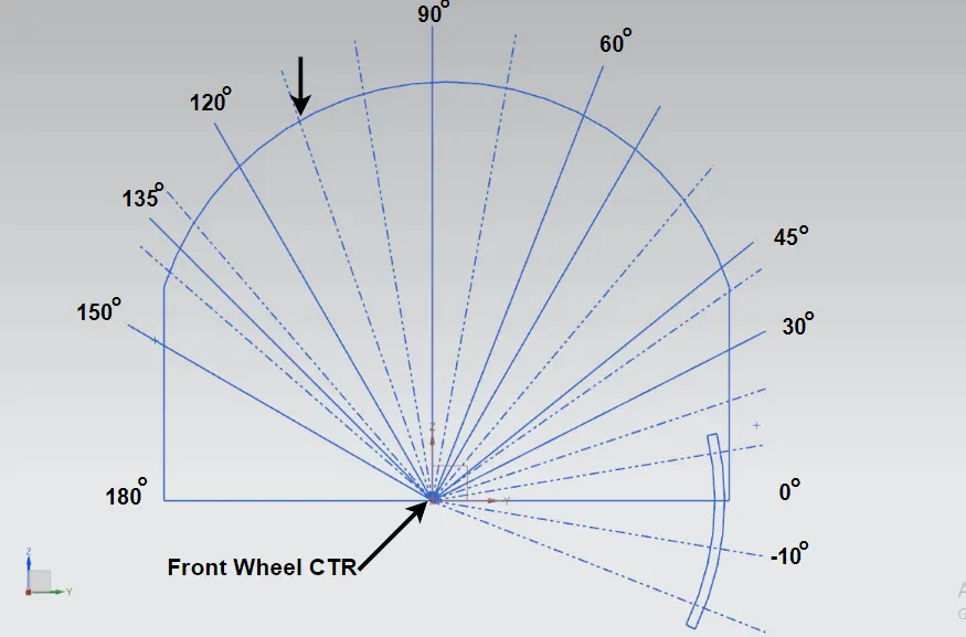
To satisfy the wheel arch radius of the fender & the wheel should be 5 mm & to be calculated for every 10 deg.point of intersection
EUROPEAN STANDARDS
To calculate firstly create the datum plane xc direction create a sketch & draw the line as per required dimensions as shown in the above picture.
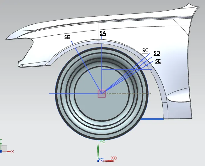
as per the european standards tghe clearance (L) should not be less the 10 mm at all the 5 points
SB,SA SC,SD,SE.
Created thehorizontal line of 180 deg from the centre of the arc. point as referance line
draw the vertical line from arc point to 90 deg. (SA)
Draw the line from arc point as 30 deg (SB)
Draw the line from arc point with 50 deg angle.(SC)
draw the horizontal line from arc point to right side & offset it upwards with 150 mm. & make the intersection point & draw the line from arc point to intersection point.(SE)
With the referance of 50 deg line & 150 mm line make the bizection line with derived line (SD)
create the intersection points
EXIT THE SKETCH & PROJECT THE SKETCH LINE ON THE FENDER BODY & MEASURE THE DISTANCE WITH SIMPLE DITANCE TOOL
The obtained measurements are the required radius as per the european standards.
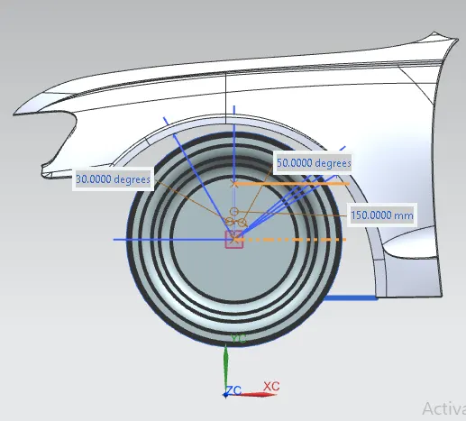
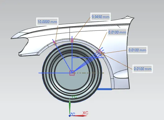
BLUE LINE ARE THE WHEEL LINES ( POINT) & PINK LINE ARE THE FENDER LINE (POINT)
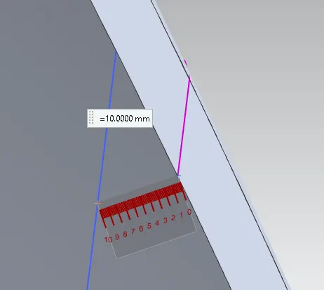
ALL THE IMAGES ARE ATTACHED ABOVE.
AS PER THE EUROPEAN STANDARDS THE VALUES I HAVE ACHIEVED.
SB 10 mm (pass)
SA 9.9 mm(fail)
SC 0.0100 mm (fail)
SD 0.100(fail)
SE 0.100 (fail)
CONCLUSION
Only SB line is satisfying the european standards 10 mm rest all are fail. as per my sketch. hence i have to discuss with the stlying team & say to give the inputs to change the stlying of the fender to satisfy the european standards.
the given fender does not satisfy the european standards.