Fender Design - Wheel Arch Challenge
Aim :
To calculate the wheel arch gap at required points and check whether the car passes the European standard.
Objective :
- Study about the different wheel arch gap standards.
- Draw the lines at the required angle and points for the European standard.
- Measure the distance at each angles and mention given model is pass or fail.
Theory :
Fender :
Fender is a part of an automobile, motorcycle or other vehicle body that frames a wheel well (the fender underside). Its primary purpose is to prevent sand, mud, rocks, liquids and other road spray from being thrown into the air by the rotating tire. Fenders are typically rigid and can be damaged by contact with the road surface.
The fender is the curved part of the car’s body that sits on top of the wheels and holds them in place. It is not only a safety component but also enhances the overall look of your vehicle. Its primary function is to shield and protect the passenger compartments by preventing sand, mud, rocks, liquids, and other roads spray from being thrown into the air by the rotating tire.
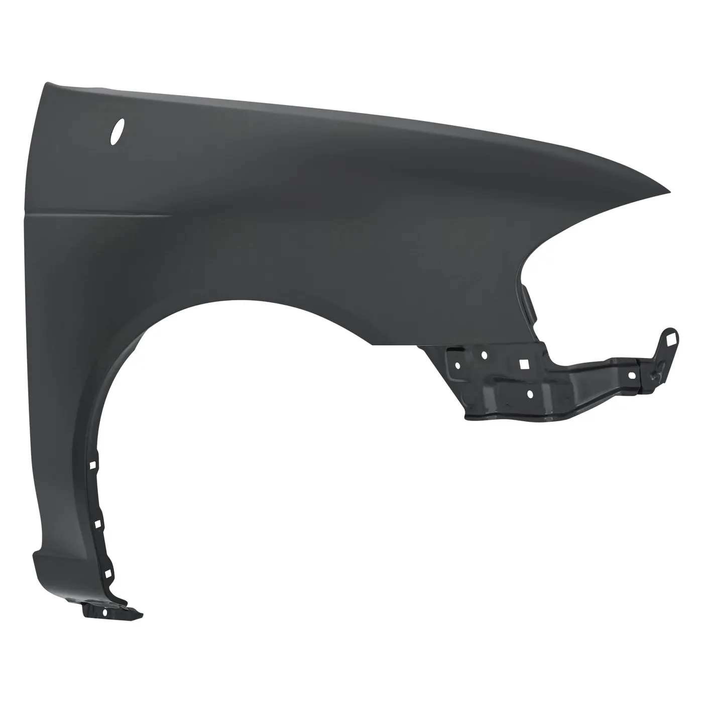
The main purpose of fenders on cars is that they shield the wheels and they protect the passenger the pedestrains and the other vehicles from stones, mud, liquid and other debris that can fly in the air because of the speeding rotating wheels while the car is running.
TYPES OF FENDER :
Full front Fender : It that cover the tire, the fender forms the wheel well surrounding the tire, and is not directly visible from above the car body. This type of fender increases the weight and scrap and reduces mielage .
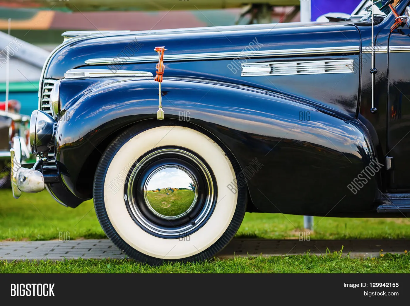
Half Front Fender : It main function is to minimise the weight and increase mileage . in Nower days Most of the OEM's manufacture Half Front Fender
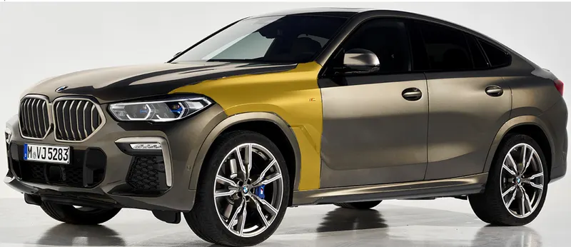
Functions of Fender :
· Car fenders limit the exposure of your car’s body and engine to external elements that are harmful.
· Fenders flares are attached to ensure that both the body and engine have minimal contact with corrosive elements.
· Car fenders provide safety to the driver and the passengers at the time of accidents or collisions. They are manufactured in a way to provide bend during front and side collisions.
· Car fenders are designed to avoid wind resistance and make your car more aerodynamic.
· Car fenders enhance the overall look of your car. Fender flares are available in distinctive designs in the market. Mostly you find universal fender flares, but you can get customized cars fenders to fit your car wheels.
DIFFRENCE BETWEEN FENDER AND BUMPER :
The main difference between bumper and fender is that a bumper is installed on the rear and front of the vehicle while the fender is installed over the front and rear wheel wells on the side of the car body. Bumpers absorb shock when cars collide with another body, while fenders prevent dirt and other particles from entering the wheel well, as well as improve the aerodynamics of the car. Fenders can also act as the extension of the bumpers as they also have the ability to absorb the impacts of minor collisions.
Wheel Arch :
It is a curved part of the fender positioned right above the wheel. The wheel Arch is designed such that it protects both the pedestrian and car cabin from mud, water rocks and other road spray. Different countries have different wheel arch regulations in place, and the wheel arch design has to comply with them to be deemed usable in that country.
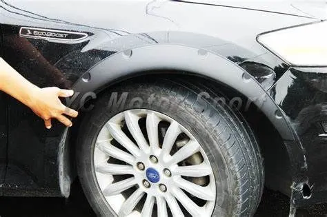
For avoiding design alterations of the same vehicle to meet the different regulations parameters are taken into consideration for design purpose.
Fender Wheel Arch Regulations :
Japan Regulations :
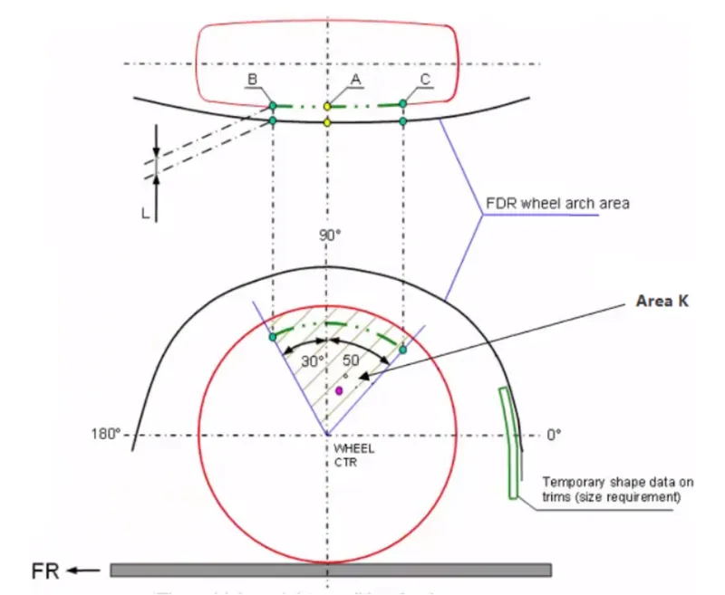
- The clearance "L" for tire, hub, cap and fender is to be measured within area K and create clearance check chart to validate.
- The value of L should be greater than 5mm at all positions.
- Wheel guard requirement : The value of "a" should be more than 5mm at line 30degree forward and 50degree rearwards from the central vertical axis of the wheel.
European Regulations :
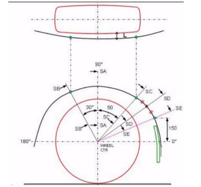
- The clearance "L" should be measured at sections SA-SA, SB-SB, SC-SC, SD-SD and SE-SE and create clearance check chart to validate.
- At all the five sections the value of L should be greater than 10mm to satisfy the European Regulations.
- Wheel guard requirement : The value of "a" should be more than 5mm at line 30degree forward and 50degree rearwards from the central vertical axis of the wheel.
US Regulations :
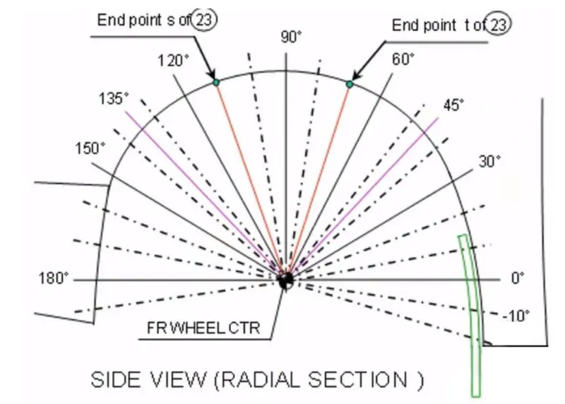
- Clearance "L" is to be checked at all positions from -100degree to 100degree and create clearance check chart to validate.
- The value of L should be greater than 5mm to satisfy the regulations.
- Wheel guard requirement : The value of "a" should be more than 5mm at line 30degree forward and 50degree rearwards from the central vertical axis of the wheel.
Calculations of wheel Arch area - European Regulations
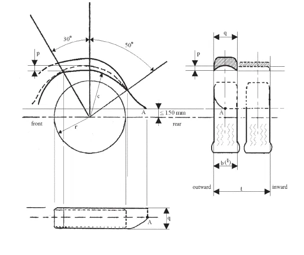
The wheel guards shall meet the following requirements with the vehicle's mass adjusted to that of the manufacturer's declared mass in running order with one additional passenger on the first seating row and the steered wheels in the straight ahead position.
1. In the part formed by radial planes at an angle of 30° towards the front and 50° towards the rear of the centre of the wheels (see Figure ), the overall width (q) of the wheel guard shall be at least sufficient to cover the total tyre width (b) taking into account the tyre envelope as well as the extremes of the tyre/wheel combination(s) as specified by the manufacturer. In the case of twin wheels, the tyre envelopes and total width over the two tyres(t) shall be taken into account.
2. For the purposes of determining the widths referred to in paragraph 2.1.1, the labelling (marking) and decorations, protective bands or ribs on tyre walls are not taken into account.
3. The rear of the wheel guard shall not terminate above a horizontal plane 150 mm above the axis of rotation of the wheels, furthermore.
4. In case of single wheels, the intersection of the rear edge of the wheel guard with the horizontal plane as defined in paragraph
5. (see Figure , point A) shall lie outwards of the median longitudinal plane of the tyre.
6. In the case of twin wheels, the intersection of the rear edge of the wheel guard with the horizontal plane as
defined in paragraph
7. (see Figure , point A) at the outside wheel shall lie outwards of the median longitudinal plane of the outermost tyre.
8. The contour and location of each wheel guard shall be such that they are as close to the tyres as possible. In particular within the part formed by the radial planes referred to in paragraph , the following requirements shall be satisfied.
9. The depth (p) of the recess situated in the vertical plane of the tyre axis, measured from the outward and inward edges of the wheel guard at the vertical longitudinal plane passing through the centre of the tyre inside the wheel guard, shall be at least 30 mm. This depth (p) may be reduced progressively to zero towards the radial planes specified in paragraph.
10. The distance (c) between the lower edges of the wheel guard and the axis passing through the centre of rotation of the wheels shall not exceed 2 × r, where the radius (r) is the static radius of the tyre.
11. In the case of vehicles having an adjustable suspension height, the abovementioned requirements shall be met when the vehicle is in the normal running position as specified by the vehicle manufacturer.
12. The wheel guards may consist of several components, provided that no gaps exist between or within the individual parts when assembled.
13. The wheel guards shall be firmly attached. However, they may be detachable either as a unit or in parts.
USE OF SNOW TRACTION DEVICES
1. In the case of vehicles where only two wheels are driven, the manufacturer shall certify that the vehicle is so designed that at least one type of snow traction device can be used on at least one of the tyre and wheel combinations approved for the driven axle of the vehicle. The snow traction device and tyre/wheel combination(s) suitable for the vehicle type shall be specified by the manufacturer under item 6.6.4 in the information document. L 292/28 Official Journal of the European Union 10.11.2010 EN
2.. In the case of vehicles where all wheels are driven, including vehicles where drive axles can be disengaged either manually or automatically, the manufacturer shall certify that the vehicle is so designed that at least one type of snow traction device can be used on at least one of the tyre and wheel combinations approved for the driven axle, which cannot be disengaged, of the vehicle. The snow traction device and tyre/wheel combination(s) suitable for the vehicle type shall be specified by the manufacturer under item 6.6.4 in the informationdocument.
3. The vehicle manufacturer shall include relevant instructions regarding the correct use of the specified snow traction devices in the vehicle handbook and this information shall be given in the national language, or at least one of the national languages, of the country in which the vehicle is offered for sale.
For calculation of clearance between wheel Arch and wheel we have to create a sketch on the outer most face of the wheel and the procedure as follows.
From the given igs file we need to open in the CATIA V5 cad and from the part file they give the fender and the wheel. So, now we need to check for the European regulations standard. Now we need to create the Datum plane at the outer most face of the wheel as shown in figure.
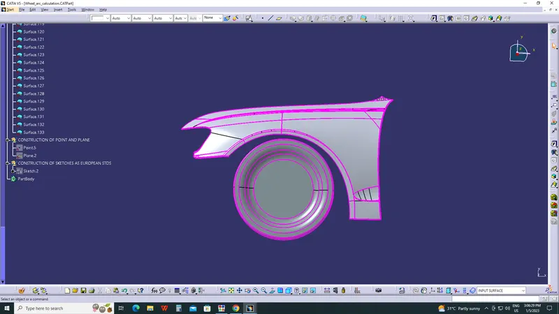
then i inserted point in the centre of top most surface of tyres and by usig that point i inserted plane .
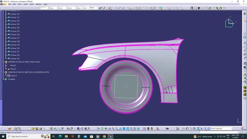
After tha in that plane we sketch the lines and the give the required angle from the reference of the European standard drawing as shown in figure.
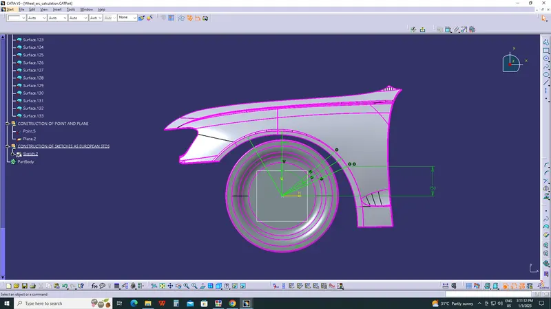
And using the text give the proper name to the lines and the dimensions are set as per the European standard as shown in the figure.
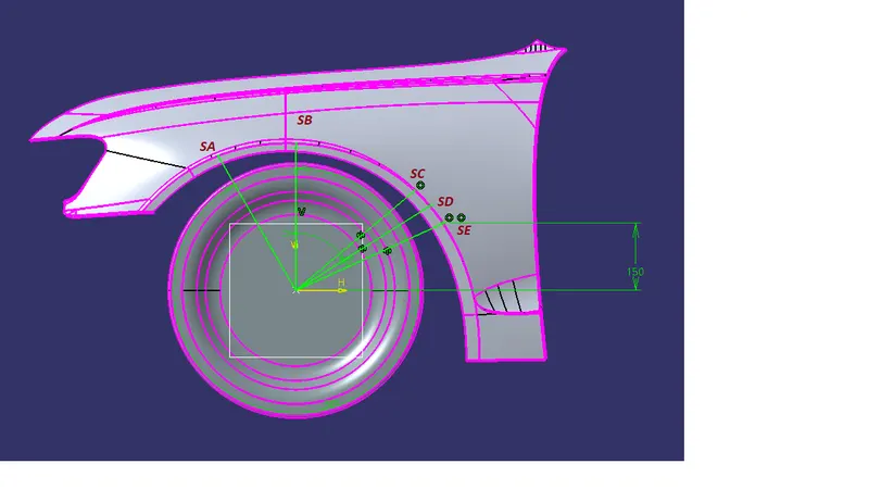
Then we need to measure the distance from the outer most wheel to the outer most wheel arch for that we add the some ponits on the face and the angle line as shown in figure.
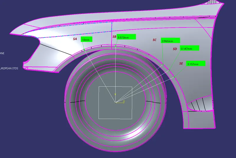
SECTION A
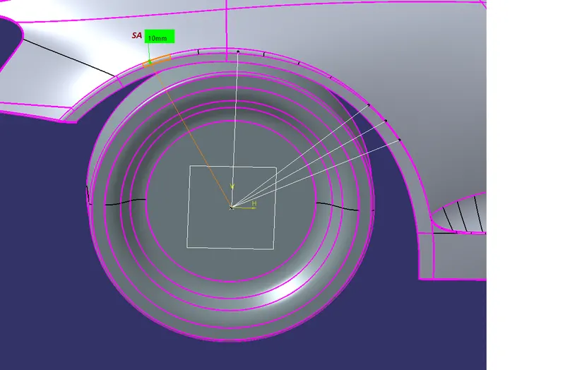
L = 10mm
SECTION B
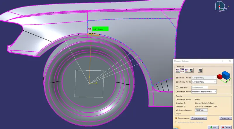
L =9.973mm
SECTION C
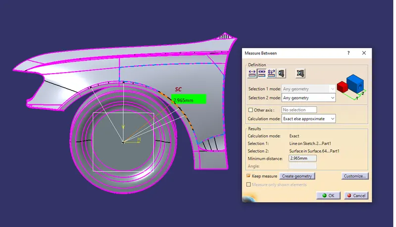
L =2.965mm
SECTION D
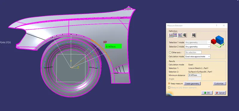
L = 0.1747mm
SECTION E
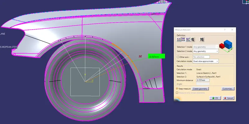
L = 3.157 mm
SECTION A, B, C , D , E
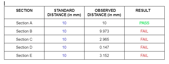
And the results are tabulated which is given below
Conclusion :
From the above results we can conclude that the Fender does not pass the European Regulations as the minimum clearance between the fender arch wheel to the outer most wheel is 10 mm and this design does not meet the this minimum clearance so this fender design is fail for the European Regulation standard.