Fender Design - Wheel Arch Challenge
FENDER DESIGN - WHEEL ARCH
Obejective :
To check wheather given fender wheel arch meets european wheel arch requirement challenge.
Wheel arch standard :
Wheel arch standard are primarly formulated to protect pedestrians from debris throw our by the wheel during automobile operation. These standards ensure
adequate setback for the wheel from the fender surface, such that debris thrown up by the wheels will be trapped inside the wheel well and therefore will not injure nearby pedestrians.
Different regions have different standards as below:
European Standard
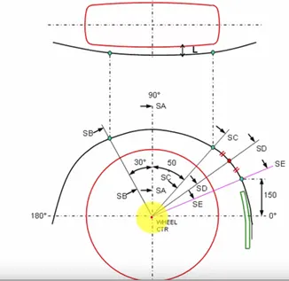
Fig 1
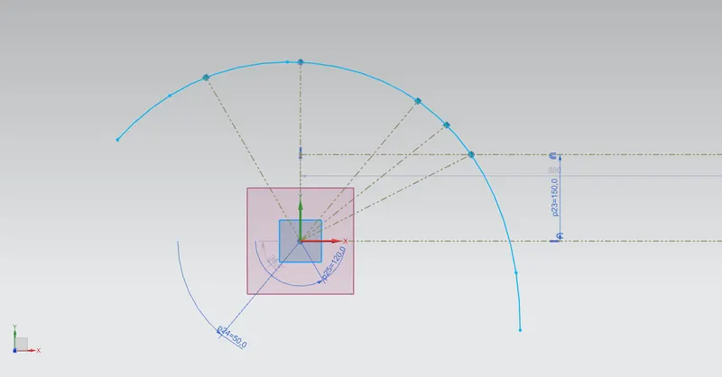
Five lines are constructed at angles relative to the horizontal line intersecting the wheel center. SA is at 90-degrees to the horizontal line. SB is forward 30-degrees to SA. SC is aft 50-degrees relative to SA. SE is formed by a 150mm vertical offset from the horizontal at the point of intersection with the wheel well/fender edge. SD is at a mid-angle between
SC and SE. These five lines are drawn on a plane containing the outermost edge of the wheel. The clearance between these lines and the wheel well/finder edge must be greater than 10mm.
US Standard
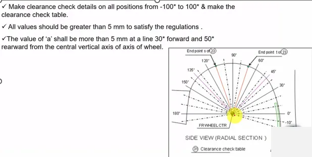
Fig 2
In the US standard, the clearance is calculated at ten-degree increments, from -10-degrees from the forward horizontal line, to -10-degrees from the aft horizontal line. The clearance for all such lines must exceed 5mm.
Japan Standard
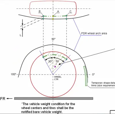
Fig 3
For the Japan Standard, measurements are taken at 90-degrees to the horizontal line, and then at 30-degrees forward of the vertical line, and 50-degrees aft of the vertical line. The clearance for these lines must exceed 5mm relative to the wheel-well/fender edge.
Wheel Arch Requirements Study
We drew six lines on the datum plane enclosing the outer wheel rim. As per the European standards, these lines included:
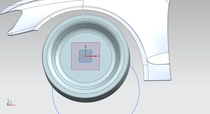
Datum plane created at the outer most edge of the wheel and created the new sketch at the plane.
First line created at 90 degree (SA) and second line created at 30 degree from first line (SB). Third created at 50 degree from first line (SC) and Fourth line created at the displacement of 150mm from the horizintal line at the edge wheelweel (SE).
Fiveth line created at s mid-angle between SC and SE.
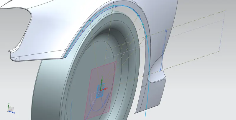
Curve from fender edge is projected in the sketch and intersection point created between five lines and projected curve. All other lines converted into reference line.
Intersection point from sketch projected in the surface fender and distance between points in sketch and points in fender suface measured.
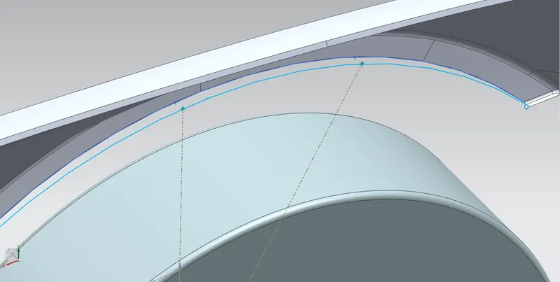
| Location | Requirement (mm) | Actual Clearance (mm) | Difference (mm) | Result |
| SA | 10 | 9.9489 | 0.0511 | Pass |
| SB | 10 | 10 | Nil | Pass |
| SC | 10 | 3.45 | 10.1137 | Fail |
| SD | 10 | -0.739 | 12.8787 | Fail |
| SE | 10 | -5.975 | 15.9755 | Fail |
Concliusion :
Given wheel arh does not meet the european wheel arch requirement standard.