Fender Design - Wheel Arch Challenge
Fender Wheel Arch Design:
Objective:
According to the European Standards, to anlyse the given fender wheel arch design whether it statisfy the standards or not. Also gives the suggestion to how much deflections should change in the design.
Wheel Arch:
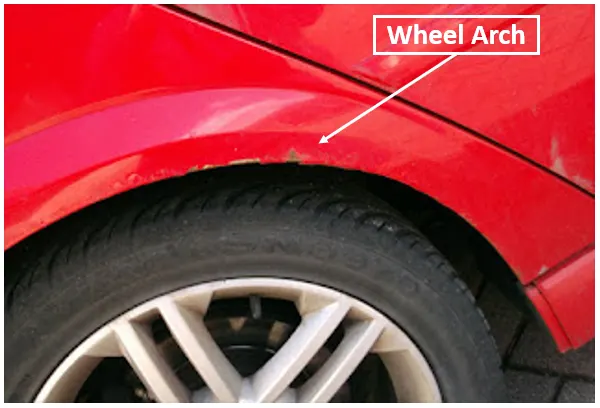
- Wheel arch is one of the important component which is integrated to the fender and placed above the wheels. Wheel arch is designed based on the wheel profile not to be protuding outside and the clearance required for the suspension and all other things.
- It is also prevents the pedestrain safety and vehicle from the stones, muds while spinning of the wheel when driving.
- There are different standards are followed to design the wheel arch. The standards are made depends upon the various road conditions and various environment region in different countries. The standards are,
- Japanese Regulation
- US Regulation
- European Regulation
Japanese Regulation:
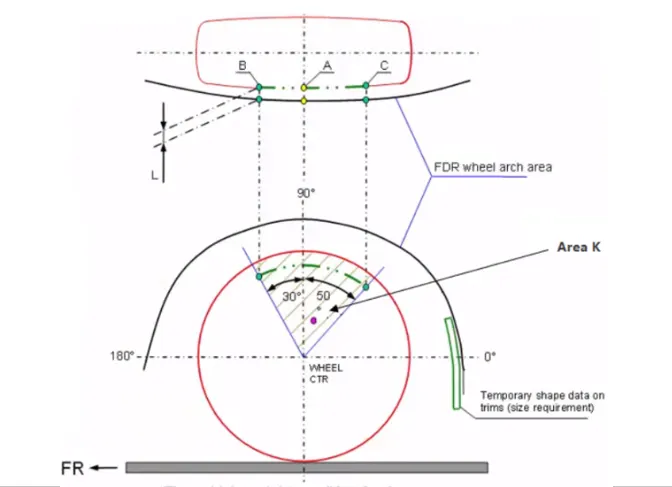
- In this regulation, L is the clearance value between the outside of the tyre and inside of the wheel arch.
- L at A is the clearance between the tyre and the wheel arch at exact vertical axis of 90 deg from the centre of the wheel.
- L at B is the clearance between the tyre and the wheel arch at angle of 30 deg forward from the centre vertical axis of the wheel.
- L at C is the clearance between the tyre and the wheel arch at angle of 50 deg rearward from the centre vertical axis of the wheel.
- The design is statisfy according to the japanese regulation, when the value of L should be greater than 5mm clearance.
US Regulation:
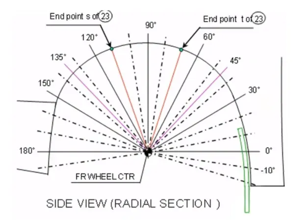
- According to this regulation, the design is statisfy when the clearance value of L should be greater than 5mm at every 10degree from -20deg of the centre of the wheel to 180deg of the centre of the wheel.
- Clearance value of L is the distance between the inside of the wheel arch and the outside of the tyre.
European Regulation:
- In this regulation, the design is to statisfy, the clearance value of L should be greater than 10mm at every sections.
- Section SB is made 30deg forward from the centre vertical axis of the wheel and Section SC, SD and SE are made rearward from the centre axis for the wheel.
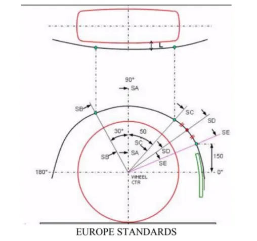
According to this challenge, the wheel arch design has been analysed based on the European Regulation,
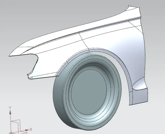
Given Input - Wheel Arch Design:
Steps followed to create the mentioned sections and calculate the clearance:
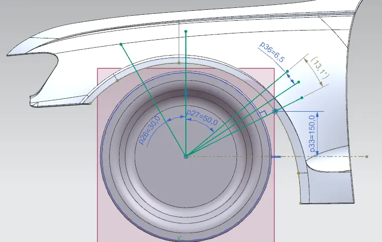
Section SA Creation:
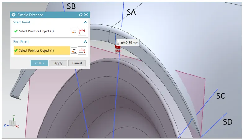
Datum Plane has been created at the outer face of the tyre and then the Line SA has created as vertical centre line from the centre of the wheel. That SA line is projected to the wheel arch surface and measured the minimum clearance between the Created SA line and Projected SA line. The clearance is 9.9489mm. So that the surface at this section is not satisfies the european standard which is not equal to or greater than 10mm, to statisfy it should be increase by atleast 0.0511mm outwards the vehicle.
Section SB Creation:
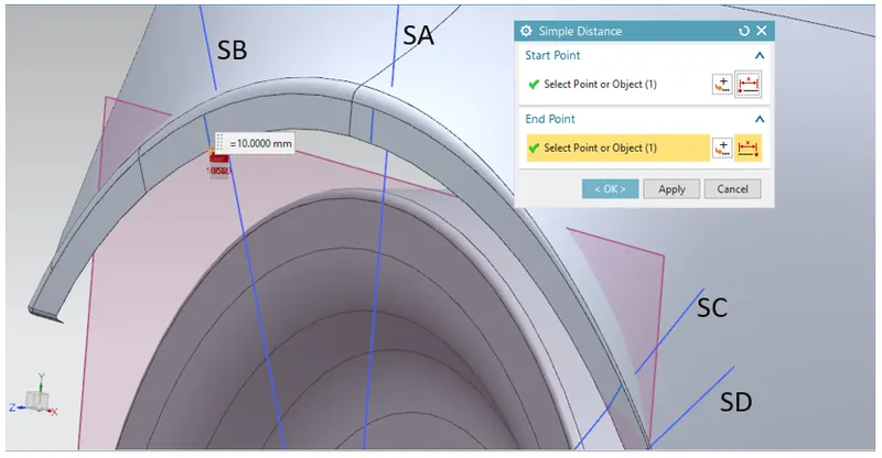
The line SB has been created at 30 degree forward from the vertical centre line(SA) of the wheel and this line is projected to the wheel arch surface. Here the measured clearance is 10mm. So that the design at this section statisfies the european standard.
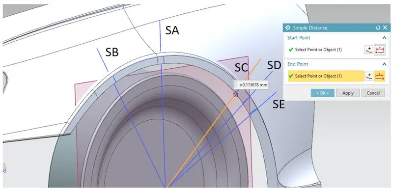
Section SC Creation:
The line SC has been created at 50 degree rearward from the vertical centre line(SA) of the wheel and this line is projected to the wheel arch surface. The measured clearance is -0.1136mm. So that the surface at this section is not satisfies the european standard which is not equal to or greater than 10mm, to statisfy it should be increase by atleast 10.1136mm outwards the vehicle.
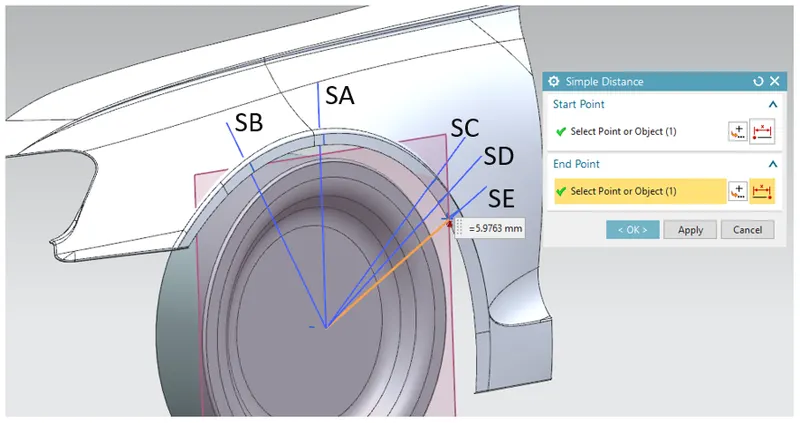
Section SE Creation:
Initially point has been created at the 150mm from the horizontal centre line of the wheel. The line SE has created along with this point. Then this line is projected to the wheel arch surface. The measured clearance is -5.9763mm. So that the surface at this section is not satisfies the european standard which is not equal to or greater than 10mm, to statisfy it should be increase by atleast 15.9763mm outwards the vehicle.
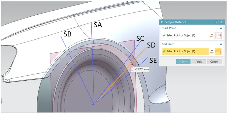
Section SD Creation:
The line SD has created at the midpoint of the lines(SC and SE). Then the created SD line is projected to the wheel arch surface. The measured minimum clearance is -2.8761mm. So that the surface at this section is not satisfies the european standard which is not equal to or greater than 10mm, to statisfy it should be increase by atleast 12.8761mm outwards the vehicle.
Analyzed Results:
| Section | Clearance(mm) | Result | Increased Clearance to Statisfy(mm) |
| SA | 9.9489mm | NOT SATISFIED | 0.0511mm |
| SB | 10mm | SATISFIED | - |
| SC | -0.1136mm | NOT SATISFIED | 10.1136mm |
| SD | -2.8761mm | NOT SATISFIED | 12.8761mm |
| SE | -5.9763mm | NOT SATISFIED | 15.9763mm |
Conclusion:
The above mentioned result are obtained by analyzed the given wheel arch design. It statisfies the European Regulation at SB section only and at remaining section are not satisfied , So that the Styling Engineer should increased the clearance in this design to satisfy the regulation standards.