Fender Design - Wheel Arch Challenge
FENDER WHEEL ARCH
AIM ; The aim of the challenge is to calculate the wheel arc area using siemens NX CAD and to check whether it is satisfying the european standards or not.
INTRODUCTION
WHEEL ARCH
The wheel arch is the semicircular part positioned above the wheel of a vehicle . The design of the wheel arch is in such a way that it protects the pedestrian and the car cabin from , engine room from the mud, rock , water ,etc. In different country the wheel arch have different regulations, and the wheel arch design has to satisfy with them to be deemed usable in that country. For avoiding design alteration of the same vehicle to meet the different regulations in different countries , the maximum values of the concerned regulation parameters are taken into the consideration during the design .
FENDER
Fender is a part of an automobile , motorcycle or other vehicle body that frames a wheel well . its primary purpose is to prevent sand mud rocks liquids and etc from being thrown into the air by the rotating tire . Fenders are typically rigid and can be damaged by contact with the road surface. the main function of the fenders on car is that they shield the wheels and they protect the passengers ,pedestrians, and the other vehicle from stones mud , liquid etc.
FENDER WHEEL ARCH REGULATIONS
JAPAN REGULATION
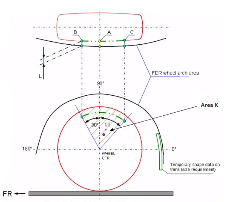
- The claearence 'L' for tire ,hub,cap and fender has to be measured within area k and create clearence check chart to validate.
- The value of 'L' should be greater than 5mm at all positions
- Wheel guard requirement the value of 'a' should be more than 5mm at line 30 deg forward and 50 deg rearward from the central vertical axis of the wheel
AMERICAN REGULATION STANDARDS
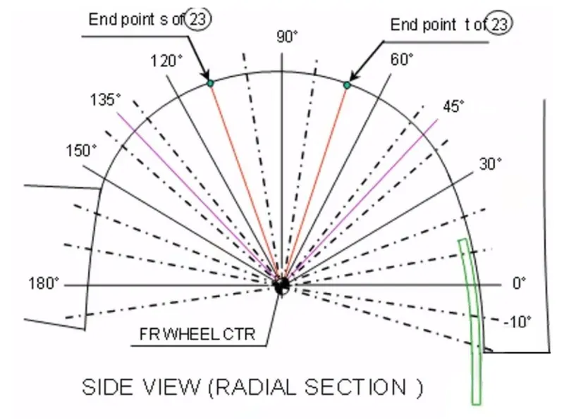
- In the american standards the clearence 'L' is to be checked at all positions from 10 deg and clearence chart to check
- The value of 'L' should be greater than 5mm to satisfy the regulation
- Wheel guard requirement the value of 'a' should be more than 5mm at the line 30 deg forward and 50 deg rewards from the cerntral axis of the wheel.
EUROPEAN REGULATIONS
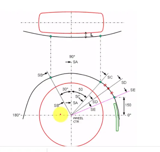
- The clearence L' should be measured at section SA-SA, SB -SB, SC- SC, SD-SD AND SE-SE and then create the clearence chart for the validation
- At all the five sections the value of L should be greater than 10 mm to satisfy the european standards
- Wheel guard requirements are the value of 'a' should be more than 10 mm atline 30 deg and 50 deg rewards from the central vertical plane.
CALCULATION ACCORDING TO EUROPEAN STANDARDS
- A horizontal and vertical axis is drawn from the centre of the wheel
- The vertical axis intersection point is labelled as 'A'.
- Similar reference are drawn at 30 deg to left and 50 deg to the right side of the vertical axis created as shown in the fig below and named it as 'B' and 'C'.
- A line of 150 mm perpendicular to the horizontal axis and normal from the normal point of fender which gives point 'E'
- And create a midpoint of the arc cut by the section C and E results in a new section 'D'.
- The value of 'L' at each sections andvalue of 'a' are found out to determine whether the fender satisfies the european standards.
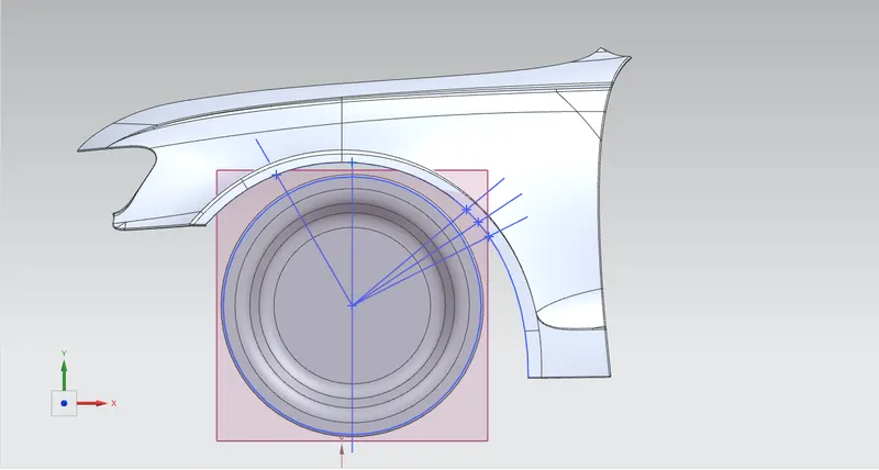
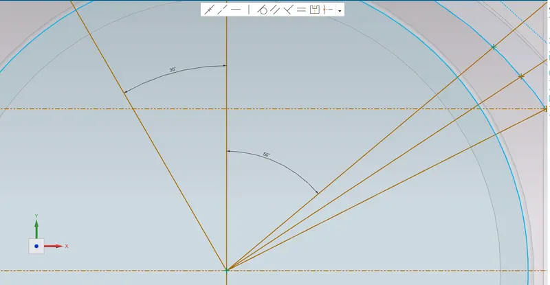
- clearence 'L' at 'A'
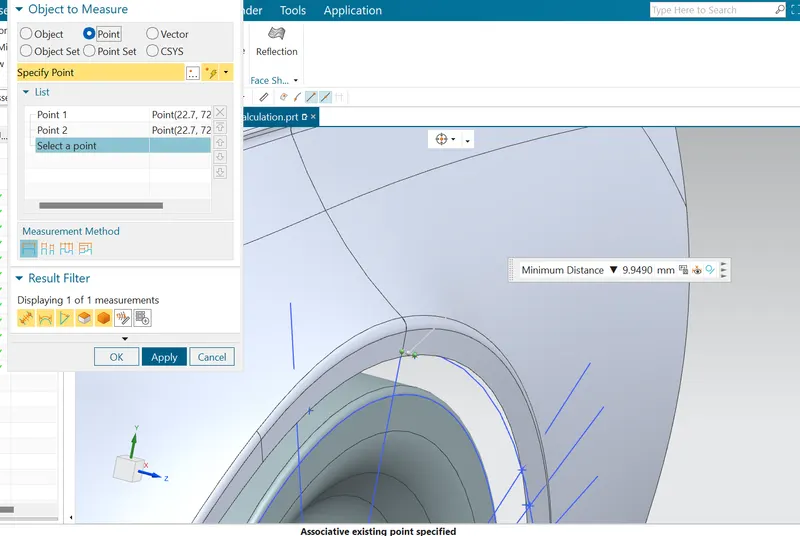
L =9.9490 , At point 'A' the clearence is not satisfying the european standards.
- Clearence of 'L' at 'B'
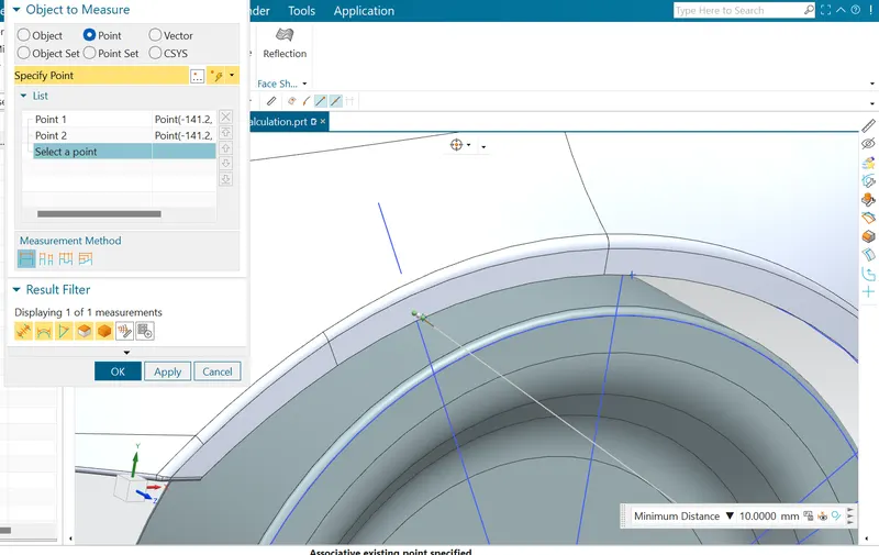
L = 10 mm , At the point 'B' it is obeying
- Clearence of 'L' at 'C'
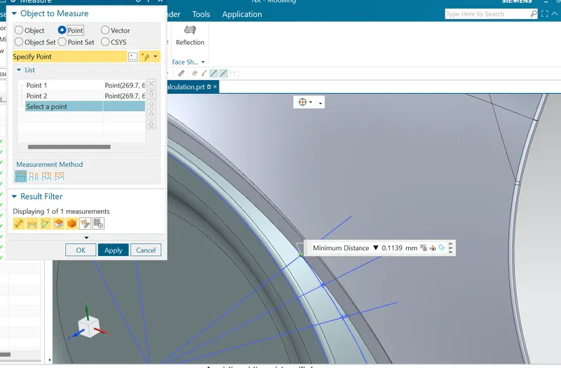
L = 0.1139mm , At point 'C' the clearence is not satisfying the european standards.
- Clearence of 'L' at 'D'
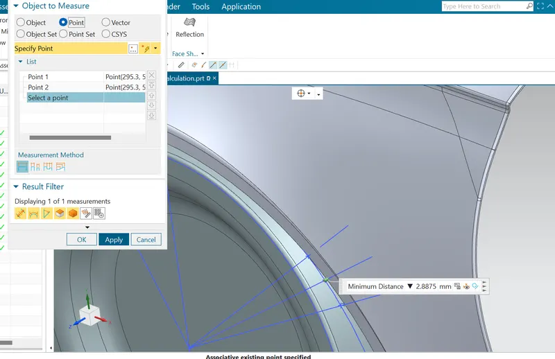
L = 2.8875 , At point 'D' the clearence is not satisfying the european standards.
- Clearence of 'L' at 'E'
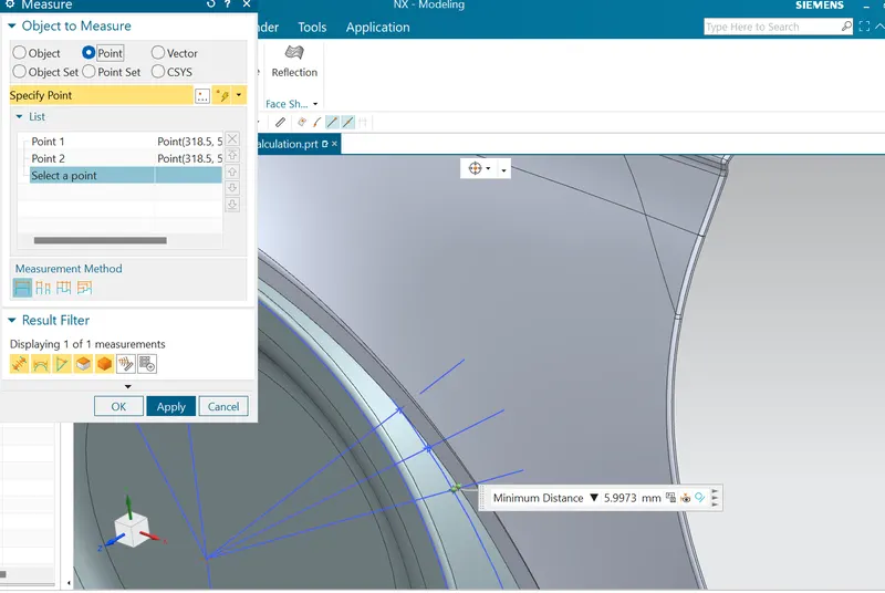
L = 5.9973 , At point 'E' the clearence is not satisfying the european standards.
RESULTS
From the above rsult we can conclude that the fender does not pass the european regulation ,as the minimum clearence 'L' between the fender wheel arch and wheel for vehicle and pedestrian safety is 10 mm , if we look in the abov result only at poin 'A' the regualtion is passing rest of the point A,C,D,E are failing , the value of L is less than 10 mm at that regions.