Fender Design - Wheel Arch Challenge
FENDER DESIGN - WHEEL ARCH CALCULATION
FENDER
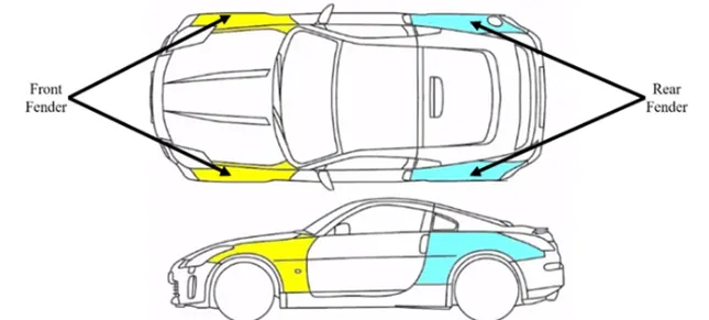
Fender covers a BIW body, traditionally to prevent water and mud spray entering the engine compartment, but also for aerodynamic purposes. When the vehicle is moving tyre picks up stones & particles are thrown in all direction, also in order to prevent impact on pedestrians hence wheel arch is used on fenders.
Fender is of two types front and Rear fender, The front fenders are designed as an individual part and the back fenders are designed along with the body pillars.
WHEEL ARCH:
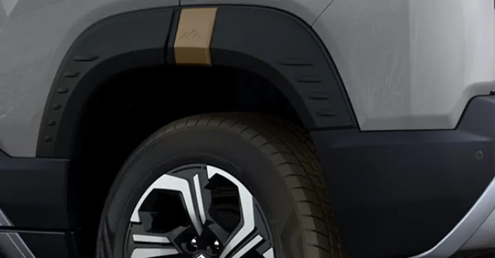
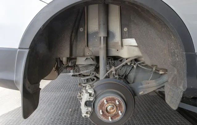
Wheel arch of the car is portion which houses the wheels of the car. It’s the semi-circular region of the fender. Wheel arch of a car will be having some standard specification. Mostly it is made of hard plastic. Which keeps cost intact. Also, easily replaceable.
The wheel cannot be outside the fender as it will lead to more chipping from the tyre. This is not good for the car and the pedestrians. So, by keeping this the pedestrian’s safety in mind, the tyre position should be inside the fender. This regulation changes according to the region. So, it is important to keep those regulations in mind while designing the fender and its wheel arch.
STANDARDS AND REGULATIONS FOR DESIGNING WHEEL ARCH:
This varies from country to country; we have standards from 3 country as an example:
- US Regulations:
- Make clearance check details on all positions from -100° to 100° and make the clearace check table.
- All values should be greater than 5mm to satisfy the regulations.
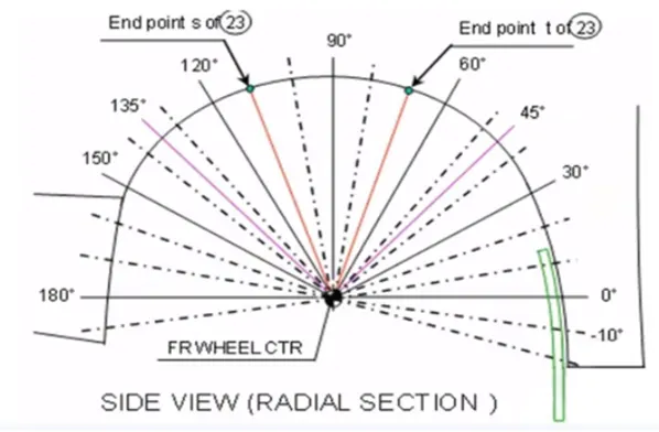
- The value of ‘a’ shall be more than 5mm at a line 30° forward and 50° rearward from the central vertical axis of the wheel
- Japan Regulations:
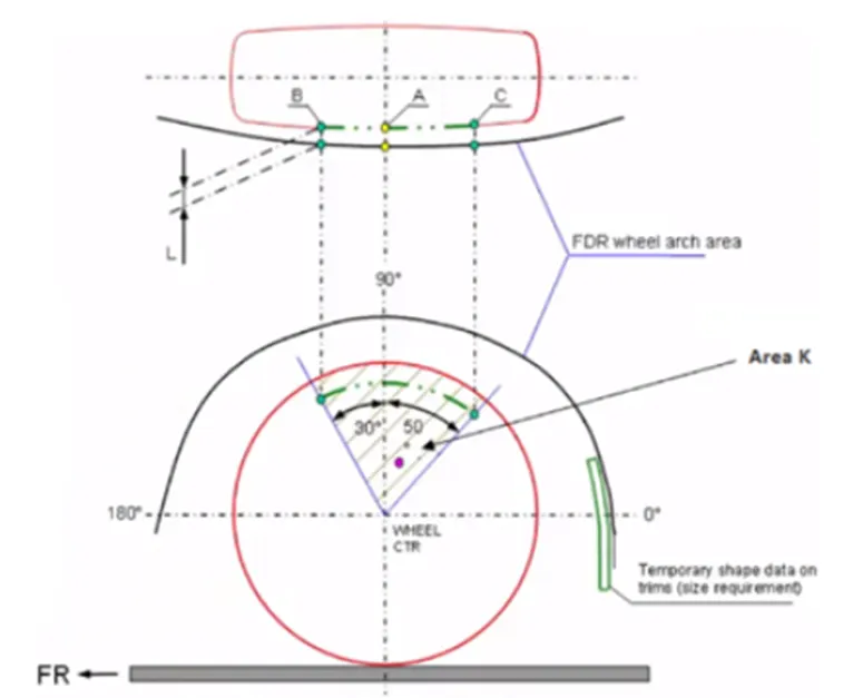
- Measure clearance ‘L’ of the tire, hub, cap & fender in three different positions within area K and produce clearance chart to validate.
- Clearance must be greater than 5mm in all three positions
- Wheel guard requirement are, the value of ‘A’ shall be more than 5mm at a line 30° forward and 50° rearward from the central vertical axis of the wheel
- European Regulation:
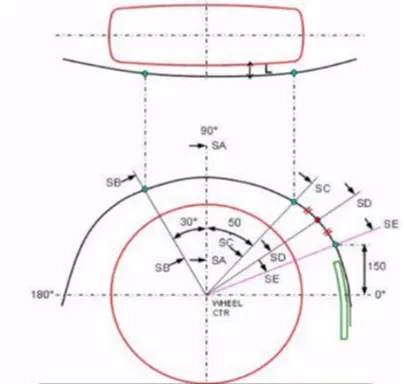
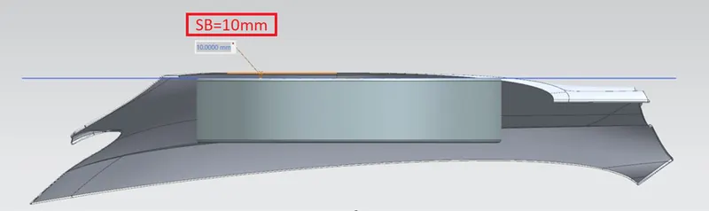
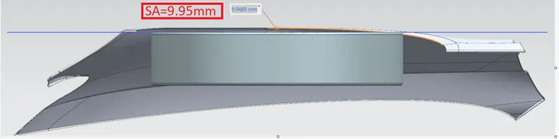
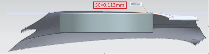
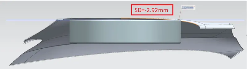
- Measure L at sections SA-SA, SB-SB, SC-SC, SD-SD, SE-SE and produce CL check chart to validate.
- At all five sections the L value should be greater than 10mm to satisfy the European regulations.
- Wheel arch requirement are the value of ‘a’ shall be more than 5mm at a line 30° forward and 50° rearward from the central vertical axis of the wheel.
CALCULATION OF FENDER DESIGN - WHEEL ARCH:
As per the Input we will be comparing the model as per the European standards:
Steps:
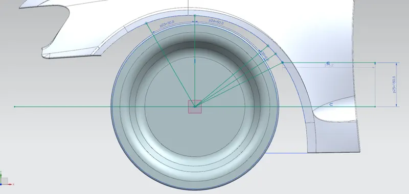
- Create a datum plane at the outermost face of the wheel.
- Create a sketch on the new datum plane.
- Draw a Horizontal and Vertical line from the centre of the wheel as a reference.
- Now create the lines to calculate SA, SB, SC, SD and SE.
- Vertical Centre line will be SA.
- SB should be vertical line angled at 30° from Centre.
- SC should be vertical line angled at 50° from Centre.
- Now offset the horizontal line to 150mm and draw line to the arch.
- From centre connect a line from centre to coincident line on the arch. This will be SE.
- SD line shall a line midpoint to SC and SE.
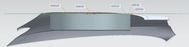
Clearance 'L' at SB = 10.00mm
Clearance 'L' at SA = 9.95mm
Clearance 'L' at SC = 0.113mm
Clearance 'L' at SD = -2.92mm
Clearance 'L' at SE = -5.98mm
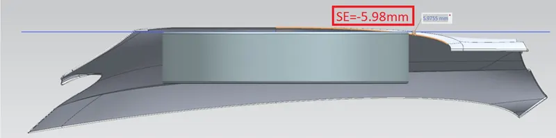
Tabulation of Results:
|
MEASUREMENT POINTS |
SA |
SB |
SC |
SD |
SE |
|
REQUIRED LENGTH |
10 |
10 |
10 |
10 |
10 |
|
MEASURED LENGTH |
9.95 |
10 |
0.113 |
-2.92 |
-5.98 |
|
REMARK |
FAIL |
PASS |
FAIL |
FAIL |
FAIL |
As per the above result, only one point SB meet 10mm clearance, rest of them don’t match hence the design needs modification. This will be sent back to design team for Further changes.