Fender Design - Wheel Arch Challenge
FENDER WHEEL ARCH
Introduction
Fender is a metal enclosure over the wheels of an automobile or other vehicle to protect against splashing of mud, stones, water etc.
The fenders are located over the wheels of the vehicle – two in the front right and left, and two in the rear right and left of your vehicle.
Wheel arches are the semicircular part of a vehicle's bodywork that allows for the wheels to be accessed. In other words, it's the metal part above the wheel. Wheel arches are also known as mud guards as they act to prevent dirt and other substances from getting up onto the vehicle itself.
The wheel arc is an integrated part of a fender assembly. It is a semi-circular part which is positioned above the wheel of a vehicle. In some countries, it is also called as an inner fender.
European Standards for Fender Wheel Arch
According to the European Standards, 5 points in particular positions at the outer surface of the wheel should be at a minimum distance of 10mm from the outer surface of the fender.
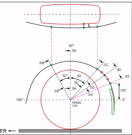
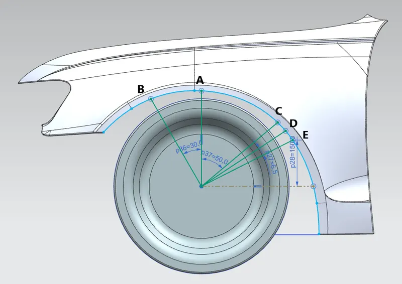
The position of the 5 points named as SA, SB, SC, SD, SE are mentioned below;
- A horizontal and vertical Axis is drawn from the centre of the wheel.
- The vertical axis intersection point is labelled as SA.
- Similar references are drawn at 30 degree to the left and 50 degree to the right of the section SA and are named SB and SC respectively.
- A line of 150mm is drawn perpendicular to the horizontal axis and the normal from that point on the fender gives us SE.
- The midpoint of the arc cut by the sections SC and SE results in a new section SD.
The value of 'L' at each section and the value of 'a' are found out to determine whether the fender satisfies the European standards as shown below.
Method followed to measure the ‘ L ‘ value at each section;
- The Fender wheel arch outline is projected in the plane wheel’s outer surface.
- The lines are drawn to mark the sections SA, SB, SC, SD, SE.
- Points are developed in the intersections regions of the lines and the projected wheel arch curve.
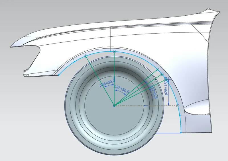
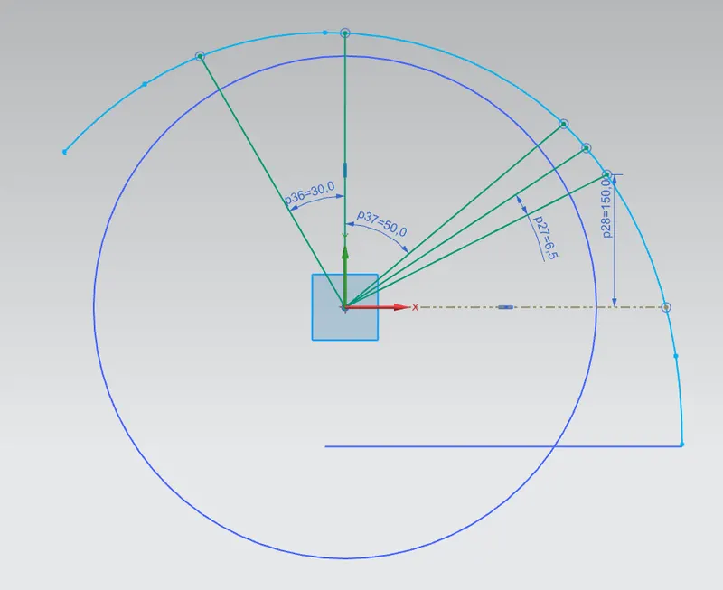
- Then the Fender wheel arch outline is projected into a plane considered as the bottom plane of an actual car.
- Then the intersection points are projected.
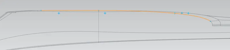

- Outer surface of the wheel is projected in the same plane.
- Lines are developed between the points the projected wheel arch curve.
- The dimensions of the lines are measured to find the respective distances in each sections SA, SB, SC, SD, SE.

Measured ‘ L ‘ value at SA
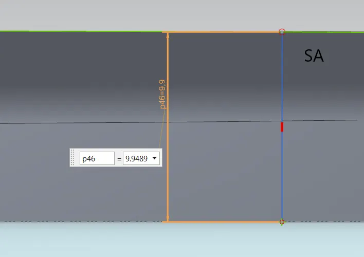
L SA = 9.9489 mm < 10 mm; Fail
Measured L value at SB
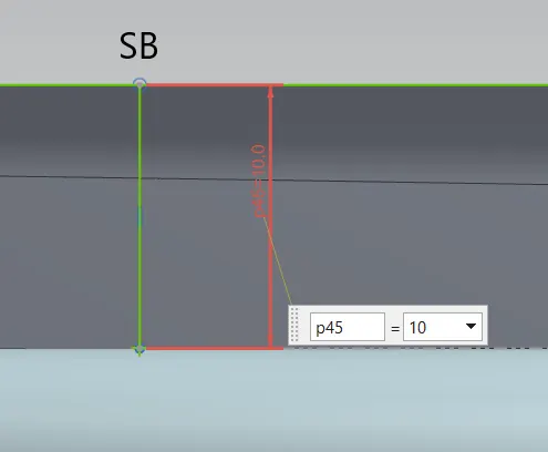
L SB = 10 mm = 10 mm; Pass
Measured L value at SC
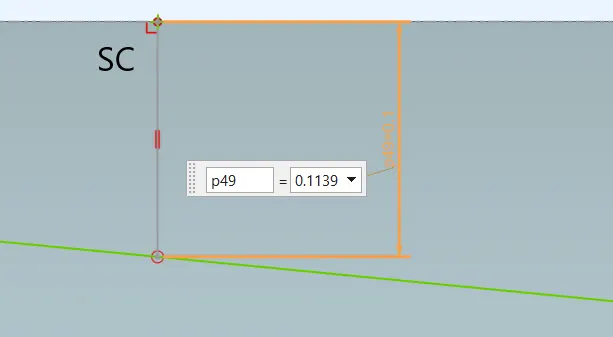
L SC = -0.1139 mm < 10 mm; Fail
Measured L value at SD
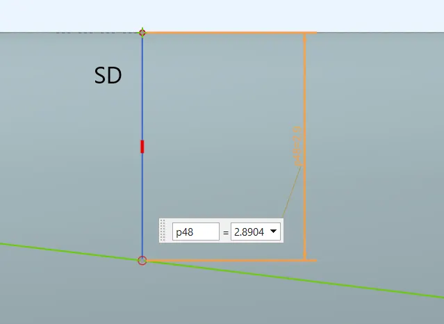
L SD = -2.8904 mm < 10 mm; Fail
Measured L value at SE
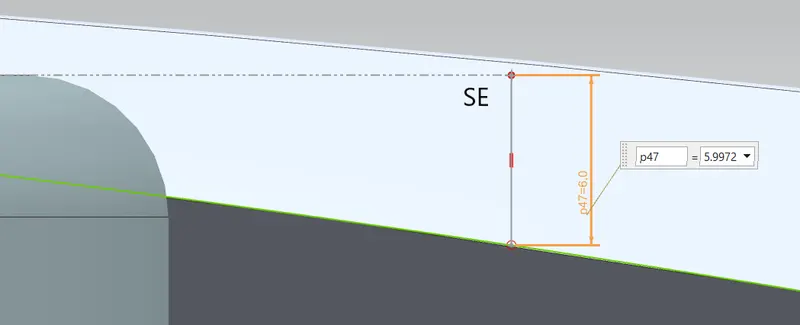
L SE= -5.9972 mm < 10 mm; Fail
Result
| Section | SA | SB | SC | SD | SE |
| L value measured in mm | 9.9489 | 10 | -0.1139 | -2.8904 | -5.9972 |
| Pass /Fail | Fail | Pass | Fail | Fail | Fail |
Conclusion
The value of L at the sections SC, SD, SE are less then 10 mm. So the given model doesn’t pass the European standards of Fender design.