Fender Design - Wheel Arch Challenge
OBJECTIVE:
To calculate the wheel arc for given Fender model, by means of the European standards regulations OK or NOT.
INTRODUCTION:
Wheel arc calculation is necessary for the fender design to pass the local regulation which are based on the local road conditions.
Wheel arch is a semi-circular area in fender, which houses the wheel well. It should have a sufficient clearance between tyre and wheel arch. So, that it doesn't touch the wheel arch area during suspension. The clearance value differ from region to region, here are few regulations.
Regulation
JAPAN
3
Check Points
Initial Step (in side view)
Lines through central point of wheel (in side view)
Clearance Check (in top view)
Clearance Condition
Vertical Line (90 degrees) 30° forward (60 degrees) 50° backward (40 degrees)
EUROPEAN
UNITED STATES
5
21
Central point of wheel with horizontal (0 degrees / (180 degrees)) and vertical (90°) axis
As per JAPAN Through vertical length =150mm^ * Through mid-arc
From -20° to 180 degrees At an interval of 10 degrees
End point of lines (side view), projected on outer edge of tire and fender in top view for evaluation of clearance
> 5 mm
> 10 mm
> 5 mm
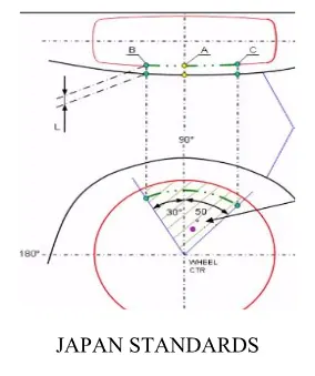
JAPAN REGULATION STANDARD:
The clearance value will be more than the 5mm at 30 degree at forward and 50 degree at backward from the central vertical line.
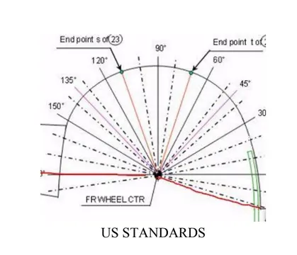
US REGULATION STANDARD:
Make clearance check details on all position from 10 to 180 degrees. All values must be greater than 5mm The Clearance Value will more than 5mm at line 30 degree forward and 50 degree backward from central vertical axis.
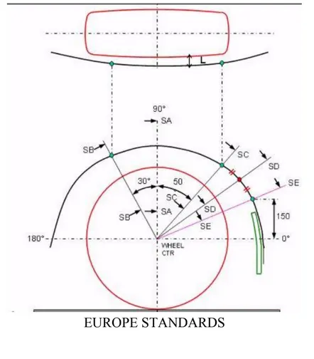
EUROPE REGULATION STANDARD:
The clearance value will be more than 10mm at 30 degrees at forward and 50 degree at backward and line 150mm above X-axis and Mid-point between 50 degree and line above 150mm.
PROCEDURE:
USEING COMMANDS: Plan,Sketch.
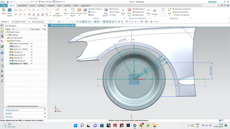
- Create the datum plane on the outer edge of the wheel.
- Create the section SB,SA,SC,SD,SE.
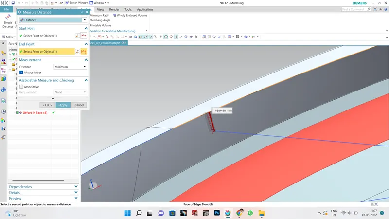
- Create the centre axis SA.
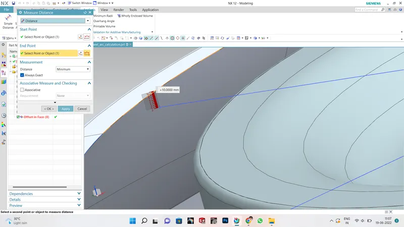
- Create the section SB by creating a inclined line of 30 degree to the centre axis i.e SA
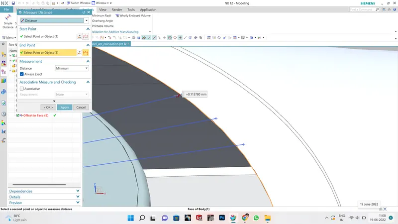
- Create the section SC by creating a inclined line of 50 degree to the centre axis.
- The section SE is created by placing the line on the fender at a distance of 150mm.
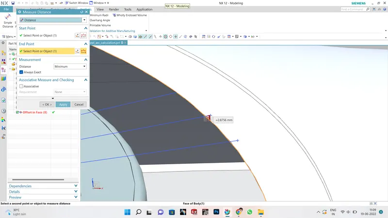
- The section SD is created by the placing on the centre between the SC and SE.
SA:
SB:
SC:
SD:
SE:
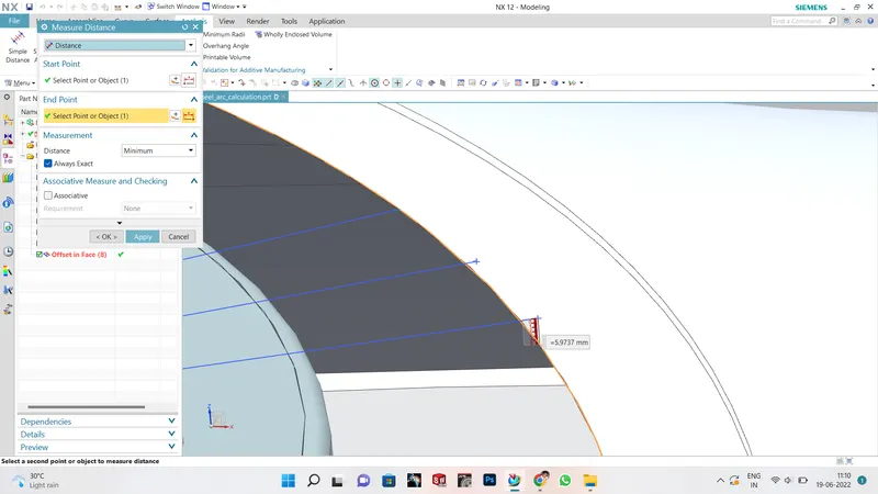
FINAL ANALYSIS RESULT:
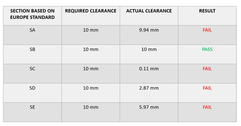
CONCLUSION:
The above model doesn't satisfy the european standards on sections A,C,D,E .