Fender Design - Wheel Arch Challenge
AIM:
To examine the Wheel Arch gap of the given fender design at required points and check whether the car passes the European standard.
ABSTRACT:
WHEEL ARCH: -
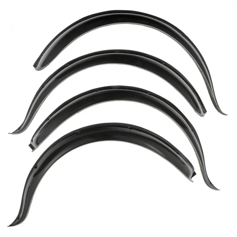
The wheel arch is the semicircular part positioned above the wheel of a vehicle. The most important body change was that the front wheel arch was cut higher into the fender. Corrosion had occurred around the splash plate at the back of the wheel arch.
FENDER WHEEL ARCH: -
Wheel Arch is the semi-circular part of the fender positioned above the wheel of the vehicle. The main role of wheel arch is it protects both passenger’s compartment and pedestrians from the projection of water, mud and stones. The wheel arch area is usually designed as a cover or shield over the tyre along its perimeter to stop any debris or stones, dirt, sand, snow, etc from getting thrown into the vehicle or onto other vehicles or pedestrians on the road. Different countries have different wheel arch regulations and the wheel arch design has to comply with them to be deemed usable in that country.
TYPES OF FENDERS:
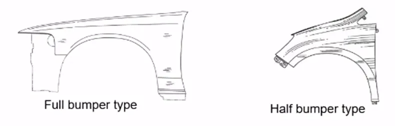
The type of fender is based upon the area covered i.e., full fender type and half fender type.
VARIOUS STANDARDS:
EUROPEAN REQULATION STANDARDS:
- Measure Clearance L at sections SA-SA, SB-SB, SC-SC, SD-SD, SE-SE and produce CL check chart to validate.
In all five sections, the Clearance L value should be greater than 10 mm to satisfy the European regulations.
Wheel guard requirement: The value of 'a' shall be more than 5 mm at line 30* forward and 50* rearward from the central vertical axis of the wheel.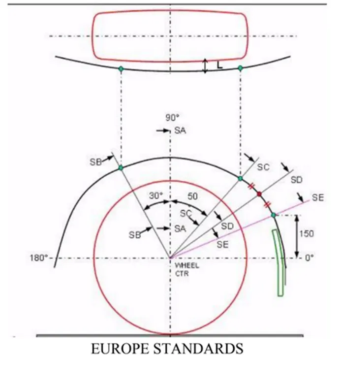
- JAPAN REQULATION STANDARDS:
Measure clearance L of the tire, hub, cap, and fender in three different positions within area K and produce a clearance check chart to validate.
Clearance must be greater than 5 mm in all three positions (i.e., at A, B, C from fender curvature)
Wheel guard requirement: The value of 'a' shall be more than 5 mm at line 30* forward and 50* rearward from the central vertical axis of the wheel.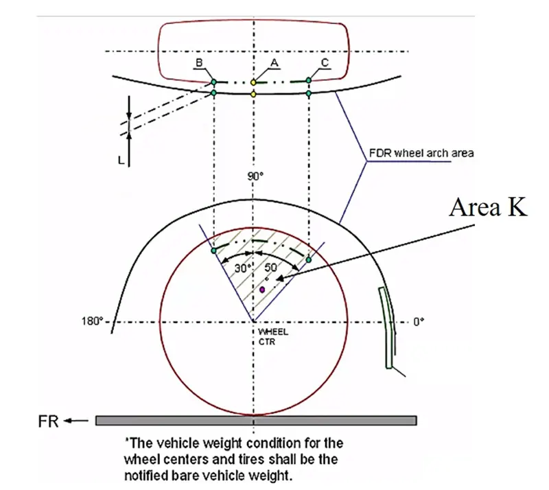
- AMERICAN REQULATION STANDARDS:
Make clearance check details on all positions from -100* to 100* and make the clearance check table.
All values should be greater than 5 mm to satisfy the regulations.
The value of 'a' shall be more than 5 mm at line 30* forward and 50* rearward from the central vertical axis of the wheel.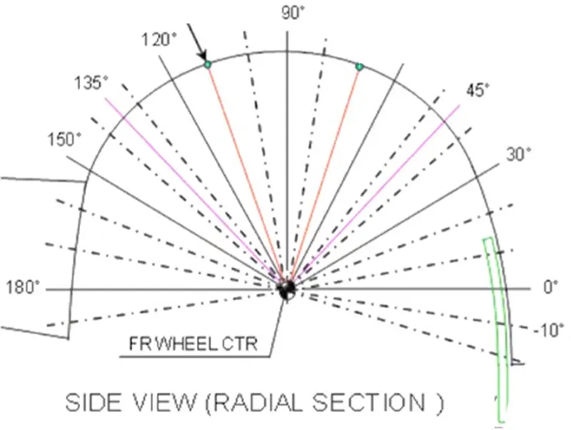
Calculation of Wheel arch area according to European Regulations:
- A Datum plane is created at the outermost face of the wheel.
- Horizontal and vertical line is created from the centre of wheel and make it reference.
- Create 30 degree and 50-degree line with respect to vertical line.
- Now take offset of 150mm from the horizontal line.
- Now create 5 points on plane and project it into the fender.
- Now measure the clearance 'L’ AND ‘a’.
Why they have different requirements?
- This is because of the road condition and also due to population density at the particular country.
- As in Japan population density is high means speed limit will be low due to which at low speed the mud particle will spread slow so it has less distance (5mm).
- While in Europe population density is less means speed limit will be high due to which at high speed the mud particle will spread fast so it has more distance (10mm).
DESIGN STEPS CONSIDERING WITH EUROPEAN STANDARDS:
Step 1: First create a plane with origin as the centre of wheel plane.
Step 2: Then sketch using lines along with the given dimensions as SA, SB, SC, SD, SE.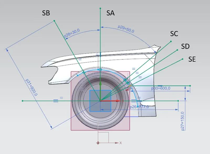
Step 3: After sketching the lines, use measurement or simple measurement option to calculate the clearance between sketch lines and wheel arc.
Step 4: The clearance between SA line and wheel arc is +10 mm also the line SA lies inside the fender so it is positive value.
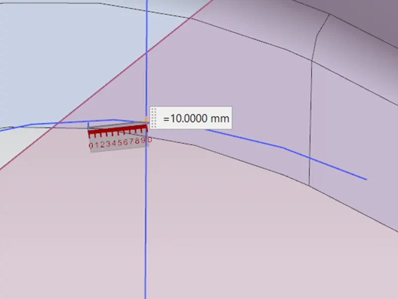
‘a’ Clearance:
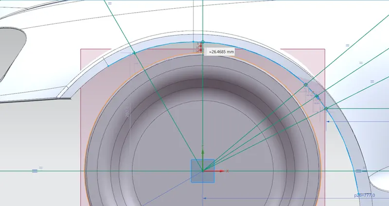
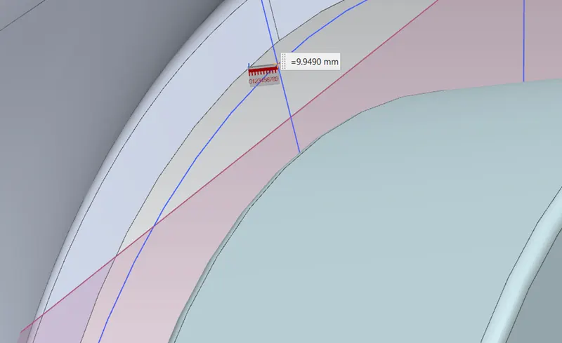
Step5: The clearance between SB line and wheel arc is +9.9490 mm also the line SB lies inside the fender so it is positive value.
‘a’ Clearance:
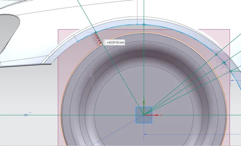
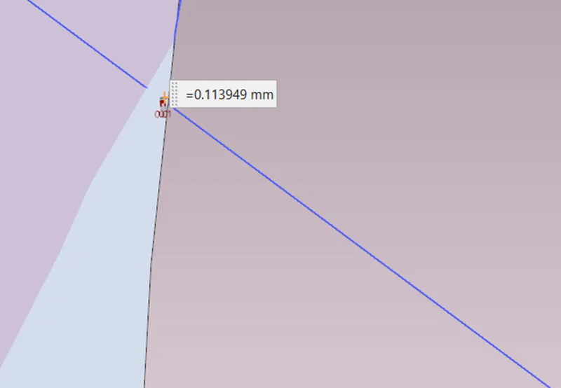
Step6: The clearance between SC line and wheel arc is -0.11395 mm also the line SC lies outside the fender so it is negative value.
‘a’ Clearance:
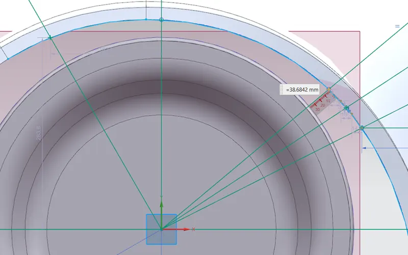
Step7: The clearance between SD line and wheel arc is -2.9112 mm also the line SD lies outside the fender so it is negative value.
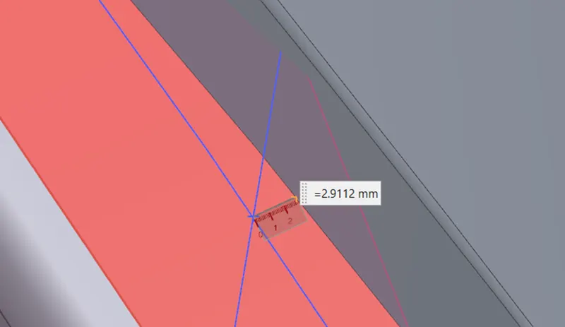
‘a’ Clearance:
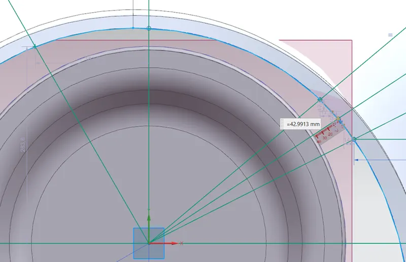
Step8: The clearance between SE line and wheel arc is -5.9973 mm also the line SE lies outside the fender so it is negative value.
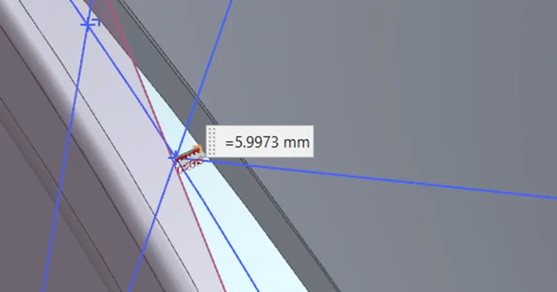
‘a’ Clearance:
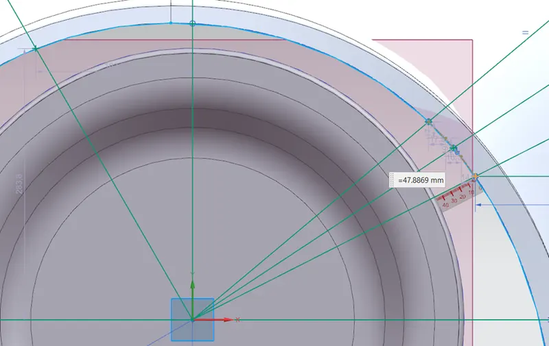
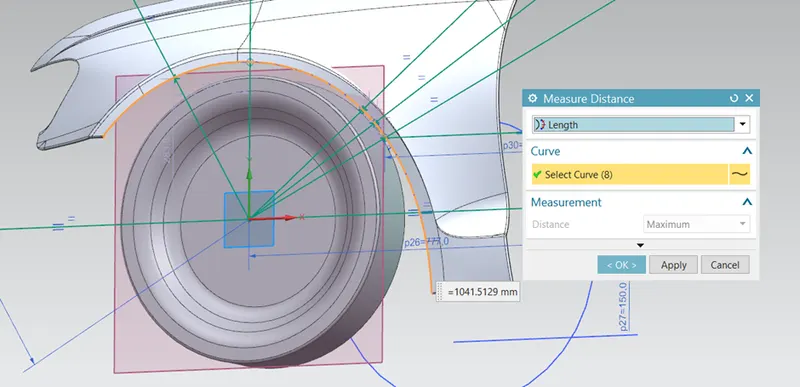
Step9: To calculate the wheel arc area, use measure function to calculate the wheel arc length by changing the length option and click the wheel arc which is 1041.5129mm.
OBSERVATION TABLE:
|
SECTIONS |
REQUIRED CLEARANCE (mm) |
MEASURED CLEARANCE (mm) |
RESULT |
|
SA |
10 |
10 |
Pass |
|
SB |
10 |
9. 9490 |
Pass |
|
SC |
10 |
-0. 11395 |
Fail |
|
SD |
10 |
-2. 9112 |
Fail |
|
SE |
10 |
-5. 9973 |
Fail |
CONCLUSION:
- As per European regulation requirements the clearance at give point should be minimum 10mm, more than 10mm can be accepted but at only one point there is 10mm clearance and other point clearance value is less than 10mm.
- SA and SB meet the required clearance value.
- The negative sign in SC, SD, SE indicates that the wheel arc is behind the wheel.
- All the a-clearances are meeting the requirement.
- Therefore, the wheel arch does not satisfy the requirements as per the European standards.
- The design of fender needs to modified by styling team.