Fender Design - Wheel Arch Challenge
Fender Design - Wheel Arch
Aim:
To Calculate the Wheel Arch gap at required points and check whether the car passes the
European standard.
Wheel arch:
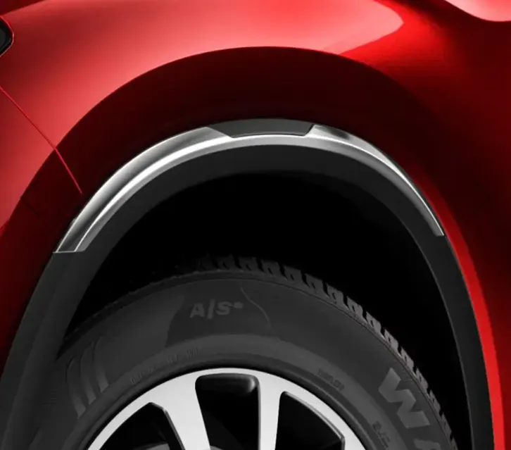
A car wheel arch is a curved or angled section of a car's bodywork that surrounds the wheel
and tire. It's designed to protect the car's bodywork from debris, water, and other road hazards that can be kicked up by the wheels. It also helps to improve the car's aerodynamics by directing airflow around the wheel and tire. The wheel arch can be made from various materials, including plastic, metal, or a combination of both. It's typically attached to the car's body using bolts, screws, or clips, and can be removed for maintenance or repair.
Fender regulations:
Fender wheel design regulations varies from countries to the country. Some of the regulations given below,
Japan requirement for fender wheel arch:
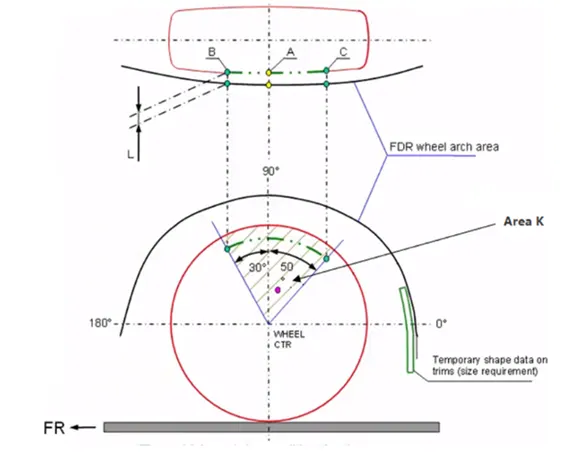
- Measure clearance L of tire, hub, cap, and fender in three different positions within area K and produce a clearance check chart to validate.
- Clearance must be greater than5mm in all three positions.
- Wheel guard requirement: the value shall be more than 5mm at a line 30˚ forward and 50˚ rearward from the central vertical axis of the wheel.
US standard for fender wheel arch:
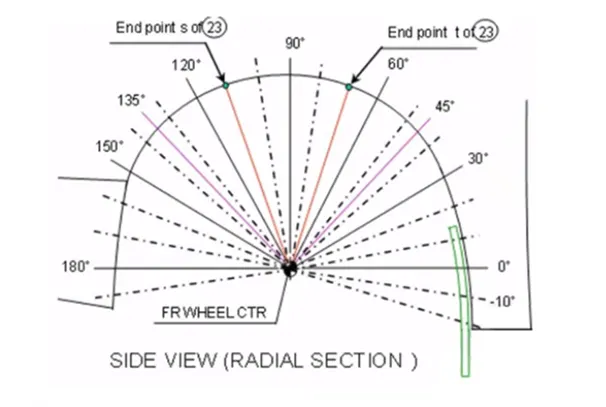
- Make clearance check details on all positions from -100˚ to 100˚ and make the clearance check table.
- All values should be greater than 5mmto satisfy the regulation.
- The value of ‘a’ shall be more than 5mm at line 30˚ forward and 50˚ rearward from the central vertical axis of wheel.
European regulation for wheel arch:
- The European regulation requires a pre- determined clearance or a minimum distance of 10 mm to be maintained between the fender and respective tire at particular points, along the tire profile as shown below.
- Wheel guard requirement: The value of 'a' should be more than 5 mm at line 30˚ forward and 50˚ reward from the central vertical axis of the wheel.
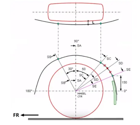
If we meet the European requirement then both the US and Japan requirements are met.
From the given model draw the 2D sketch and mark all the points as shown below,
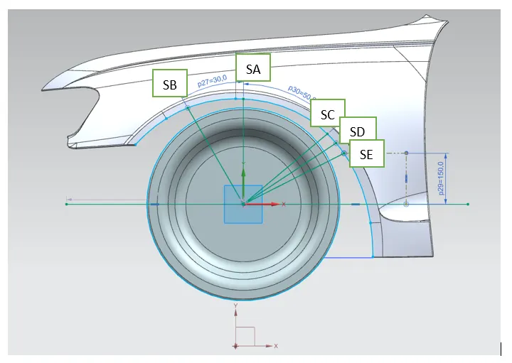
Clearance (L):
At section SA-SA, L = 10mm
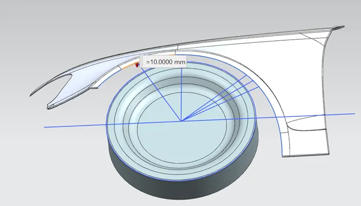
At section SB-SB, L = 9.949mm
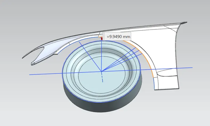
At section SC-SC, L = -0.1138mm
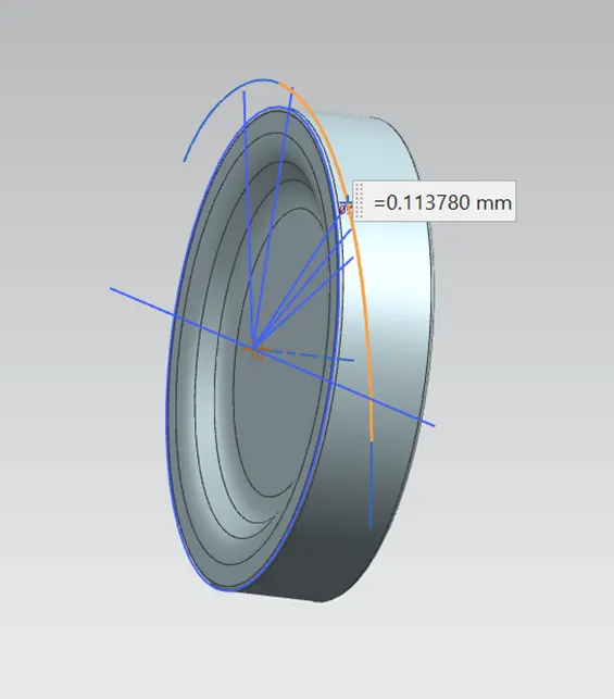
At section SD-SD, L = -2.8786mm
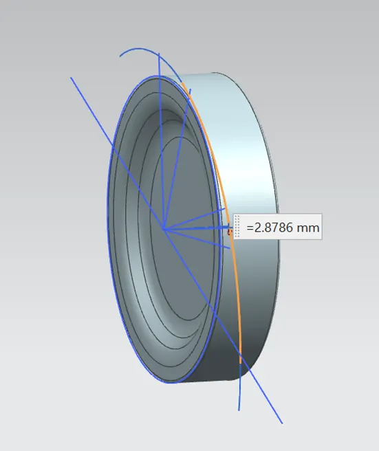
At section SE-SE, L = -5.9757mm
Measurement over each area:
|
Section |
Clearance (mm) |
Result |
|
SA-SA |
10 |
Fail |
|
SB-SB |
9.949 |
Pass |
|
SC-SC |
-0.1138 |
Fail |
|
SD-SD |
-2.8786 |
Fail |
|
SE-SE |
-5.9757 |
Fail |
Conclusion:
From the calculation we found that section SB-SB only met European requirement and all other section failed. Hence, we have to change the wheel arch design.