Fender Design Challenge
INTRODUCTION :-
WHAT IS FENDER :-
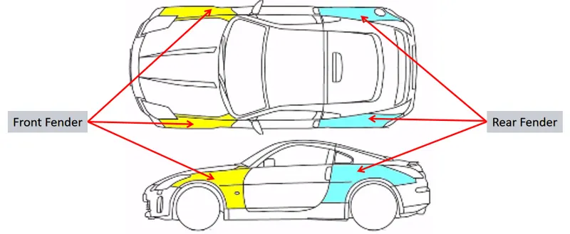
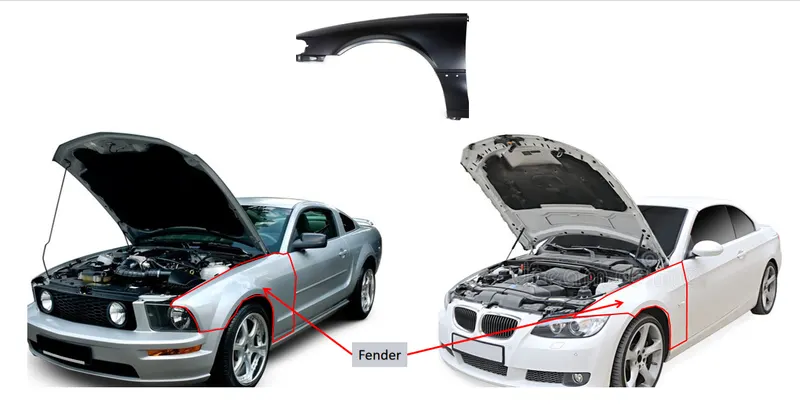
Normally rear fender has integrated with body whereas front fender is separate assembly component. This front fender is one of the side closest components to the engine compartment. The major function of this front fender is to avoid the chipping inside the engine compartment. In general during motion of the vehicle the wheels or tyres pick up some sand, mud particles, liquids and other road spray particles. So the front fender helps to prevent these types of road particles throwing into the engine compartment. The fender having a big plastic component which lies on the fender arch area, that plastic component is protecting the engine compartment. This fender plays a major role in case of pedestrian safety when they are attacked. While rotating, the mud particles on tyre may tend to chip outside and hit the pedestrians. So this anti chipping of fender will help to avoid such type of attacks. So while designing the fender commodity we should remember and implement these types of mandatory safety requirements.
TYPES OF FENDERS :-
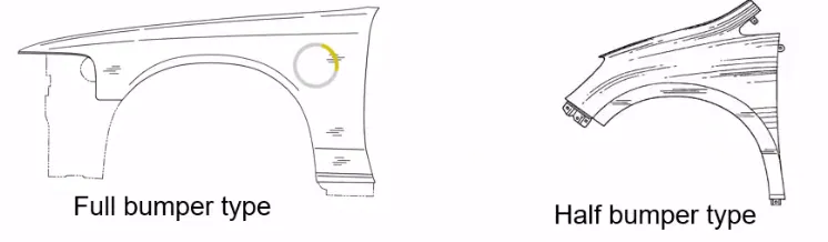
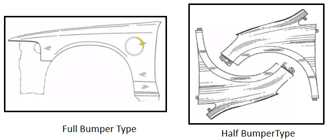
In now a days fenders are devided into two types they are :-
- Full bumper type :-
The full bumper type fenders are mainly used in old cars .
- Half bumper type :-
Now a days all automobiles are runs with half bumper type fenders. because it is basically related to scrap management. Half bumper type leads to less wastage of the blank.
SOFTWARE USED :-
CATIA V5
FEATURE TREE :-
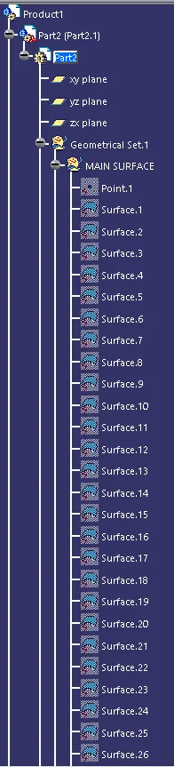
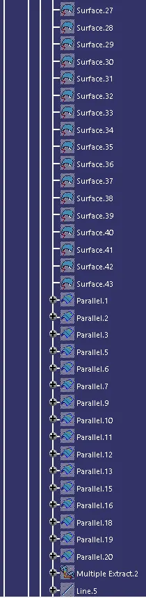
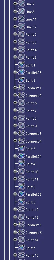
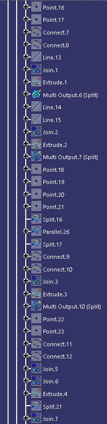
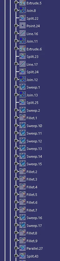
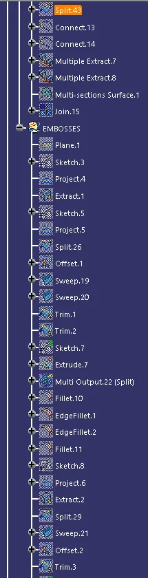
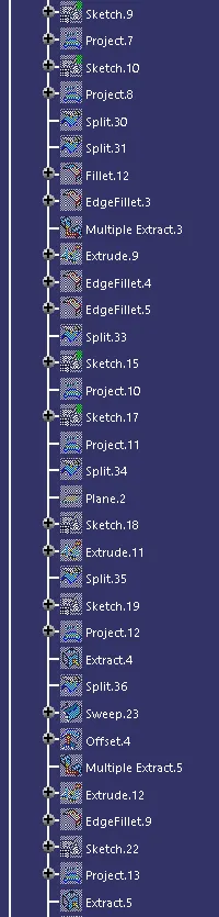
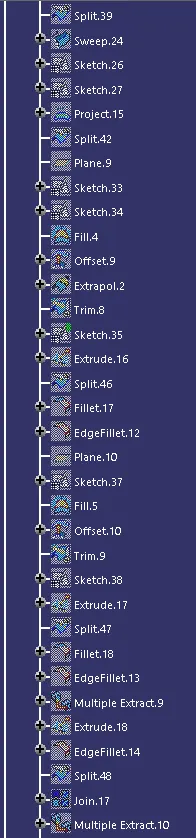
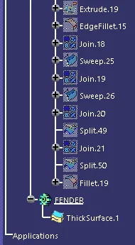
FENDER DESIGN :-
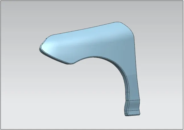
CLASS A :-
The class A surface is provided by the styling team. We have to create the fender mountings for the given class A.
FENDER MOUNTINGS :-
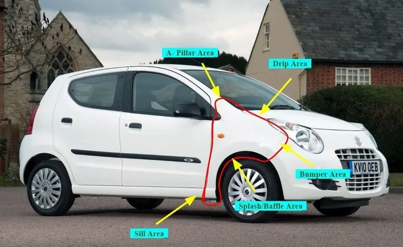
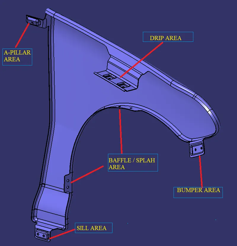
1.DRIP AREA :-
master section for Drip area :-
It is the most important mounting unit of a fender. It is connected with the engine compartment and therefore a lot of design constraints are to be followed while designing the drip area.
It should have sufficient clearance from the front and rear end of the fender to accommodate the Cowl mounting region and the Headlamp housing unit respectively as shown in the figure.
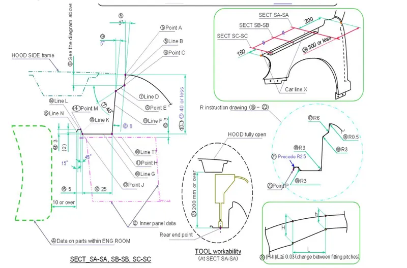
The Master Sketch provides the linear and angular measurements for designing the drip mount after taking into considerations various factors like Hood opening, Tool workability, aesthetics (since Fender is a styling surface), Spring Back effect due to exceeded length etc the given model is created .
.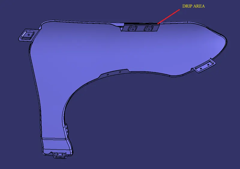
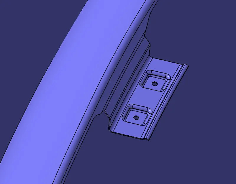
Fig a :- Position of Drp area fig b :- Drip area
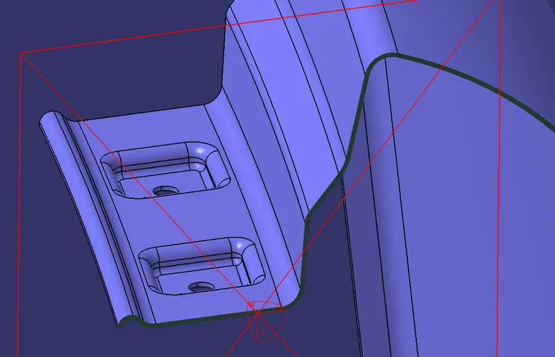
Fig c :- Cut section view
2.BUMPER AREA :-
The bumper mounting area is created at the place where fender is fitted to the bumper.
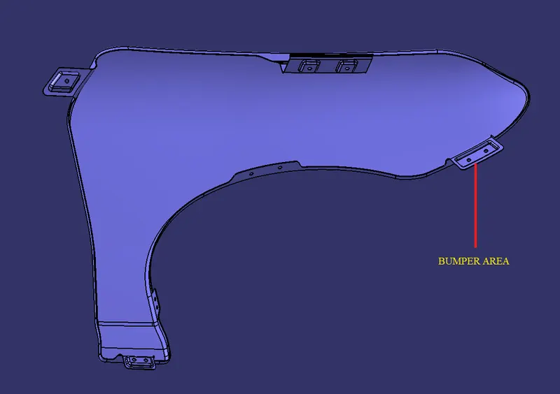
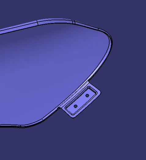
Fig a :- Position of Bumper area Fig b :- Bumper area
3.SPLASH OR BAFFLE AREA :-
The baffle is the black coloured part over the tyre. It is press fitted.
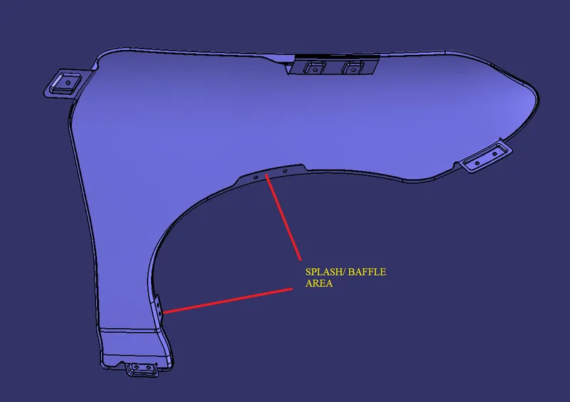

fig a :- position of Baffle area Fig b :- Baffle area
4.A PILLAR AREA :-
A pillar region is mounted to the A-pillar frame of the chasis so that it is rigidly attached to the body of the car.
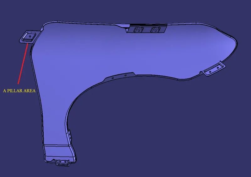
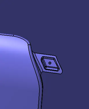
Fig a :- Position of A pillar area Fig b :- A pillar area
5.SILL AREA :-
The sill area is the area where the fender is mounted to Floor rails by Bolts.
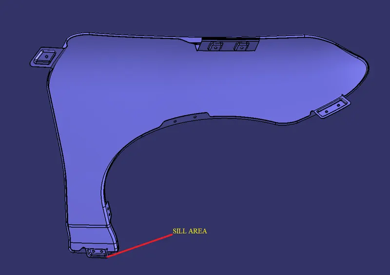
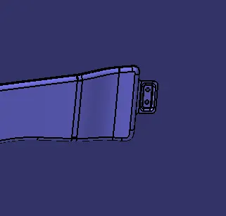
Fig a :- Position of Sill area Fig b :- Sill area
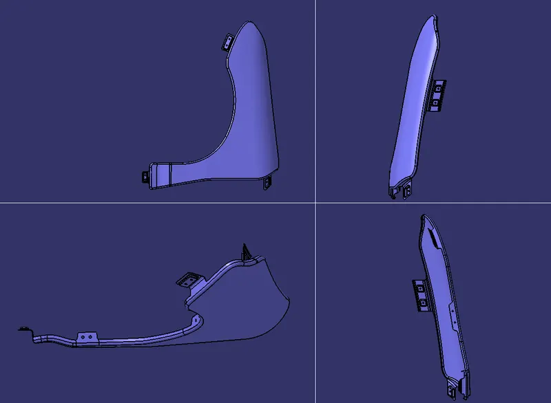
PART IMAGES :-
MANUFACTURING PROCESS :-
Generally the manufacturing of sheet metel are involved following steps
1. Process planning: The purpose of process planning of automotive panels is to identify the number of operations, the tasks in each operation, and the content of each task. This researching proposes an automatic reasoning procedure based on expert experience and the laws of physics.
2. Blank size calculation.
3. Trimming task: The trimming task is separated into two parts.
4. Restriking task: The restriking task is necessary when surfaces deform because of springback after drawing and trimming, or the accuracy requirement is high because a surface overlaps another surface of another panel during assembly. To over come spring back of sheet metal Restriking is required.
5. Piercing task: Each hole feature requires a piercing task. Hole features can be classified as basic holes, lock holes, and enlarge holes based on their different functions during assembly. A basic hole is for locating the panel, and a lock hole is for locking panels.
6. Burring task: Removing the sharp edges and harmfull burs from the component.

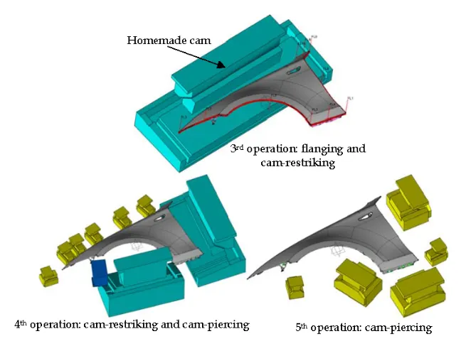
If some groups cannot be shaped while drawing. undercuts exist in the drawing direction. When a group cannot be drawn or trimmed successfully and modeling is complex, the group is shaped by two forming tasks. A flanging task is first used to bend the die face into a transitional shape and the restriking task is then used to form the transitional shape to product shape.

fender requires five operations in the result of process planning. First two operations are for drawing and trimming, and suitable standard cams are chosen or the size of homemade cams is reasoned based on features.
CONCLUSION :-
Fender mountings i.e, Drip area , Bumper area, A pillar area , Sill area , Baffle areas are created for the given fender class A by following all design rules and master section references.