Fender Design Challenge
Objective
To design the five mounting points to the front fender acording to the master section provided and elaborate the manufacturing process.
Fender
Fender is the part of an automobile that frames a wheel well (the fender inside ).
FRONT FENDER is a separate closure component. it is one of the side closing component for the engine compartment and the major role is to avoid chipping inside the engine compartment, during motion , the whwwl tries to pick up some sand and mud particles and some small particles , and throw it inside the car , and this fender will be helpful in preventing them heating inside the engine compartment and this fender have a plastic part and plastic part are lying on the wheel arch area .
its primary purpose is to prevent sand, mud , rocks, liquids, and other road spray from being thrown into the air by the rotating tire.
when the vehicle is moving , tires picks up stones and other and hurl them in all directions .
Fenders basically present to prevent any injuries to pedestrains and contain the motion of these particles.
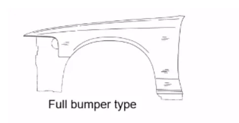
There are two types of fenders , they are
1) full bumper type
2) half bumber type
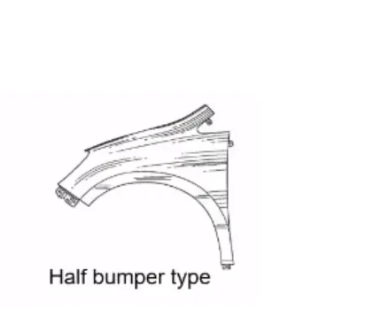
Presently we are using the half bumper type, because in full bumper type , the blank what we used to create the full bumper type is really large and due to this , we have a wastage of material also it increases the weight of a car, but in a case of half bumper type, it has a possibility to reduce the scrap , this is what is called scrap management. so we use half bumper type as it reduces the materal usage, so to reduces the cost , results to this customer will get the car having a better fender and having a cheaper price.
Wheel arch :
It is having some standard specifications, as when we see our car from the front, if the wheel is outside the fender, it does a more chipping , and this causes a llot to the pdestrain and also to the car.
so to have thr pedestrains safety in mind , we will have to position the tyre wheel inside the fender.
for every region, we have differnt regulations in the globe on the pedestrains safety for the wheel arch requirement.
1. japan requirement ( L must be greater then 5 mm ) AND ( a is greater than 5 mm )
2. US Regulation requirement ( L > 5 mm ) AND ( a > 5 mm )
3. European Regulation requirement ( L > 10 mm ) AND ( a > 5 mm )
In all the above regulation requirement we measure the clearence values from the fender and wheel arch according to the regions and road conditions. generally we measure the clearance L of tyre, hub , cap , and fender in the three positions within area k and produces clearance check chart to validate (distance horizontal value) AND vertical axis of the wheel , that is value a .
Wheel arch diameter is much larger than the diameter of the tyre , because they do not move with the suspension and consequently must be large enough to allow the full range of tyre motion on the suspension without touching the inside of the fender.
Mouting:
There are 5 mountings points in a fender design .
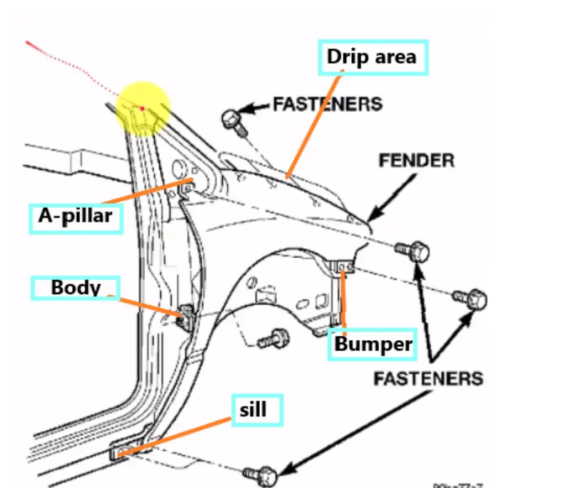
1. BUMPER
2. A PILLAR
3. SILL
4. BAFFLE
5. DRIP AREA
Design Consideration taken while designing FENDER.
- In this , emboss are provided to increase the stiffness of the mounting
- Smooth curves are designed for easy manufacturing of panel.
- DARTS are provided to drip area mount to give structual support and extra strengh.
- for the fastener to be added in the hole , 5 or 10 mm relief is provided from the flat surface
- fillets should be provided , in the region in order to prevent from stress concentration.
- Thickness of fender is 0.75mm
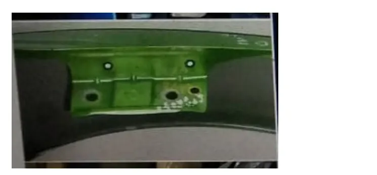
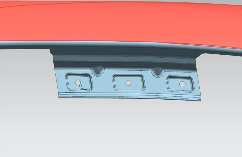
DRIP AREA :
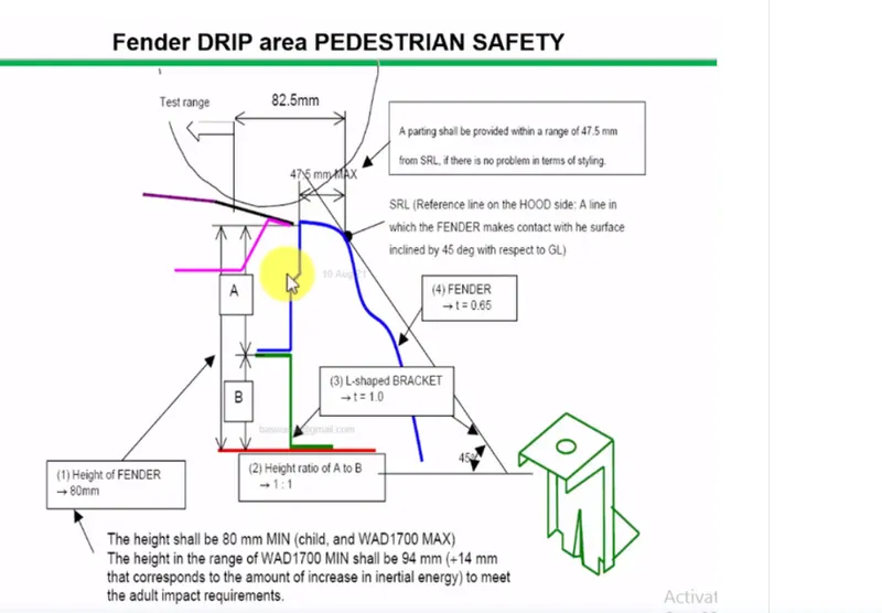
It is the joining between the fender to the engine compartment, this has a lot of design constraints to be followed.
The major thing in this drip area is the gap which we provided from the rea end of the fender and front end of the fender.
Cowl top part will be carrying the wiper motor and its instruments. to have sufficients mountings space for the cowl top , minumum clearance values need to be 200 mm from the rear end of the fender.
simillarly, the for the head lamp housing unit, sufficiently placed , minimum clearanace values nedds to be 150 mm from the front end of the fender.
To develop the fender drip area we need a master section which is provided.
Dart is provoded in the mounting drip area section to increase the strength.
we generally used fastners because the fastners regions are anyways closed.( means that fasteners will not be able to seen , as it hide by other parts in the fender ) so fastners will not going to have any impact aesthetically.
SILL MOUNTING AREA :
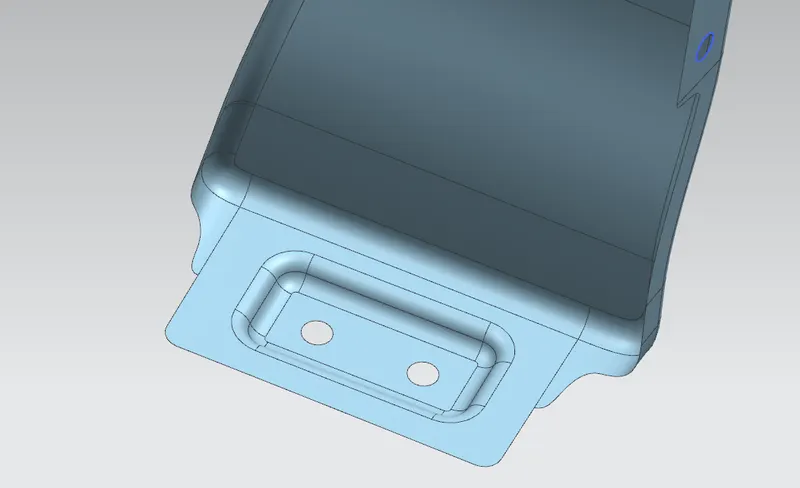
This mounting is done on the bottom part of the fender. It is used to connect the floor and the sill body. it has provided with emboss and holes.
A PILLAR :
We have total 3 or 4 pillar depending upon the type of car we have namely A , B , C , D . This A PILLAR is combined the body to the roof of the car. This mounting is done to provided with ribs to strengthen the part. It is taken from the place at cowl is placed.
BUMPER MOUNTING AREA :
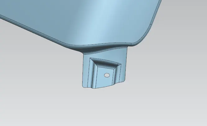
It is used to fix the plastic bumper to the fender with the help of the fasteners.
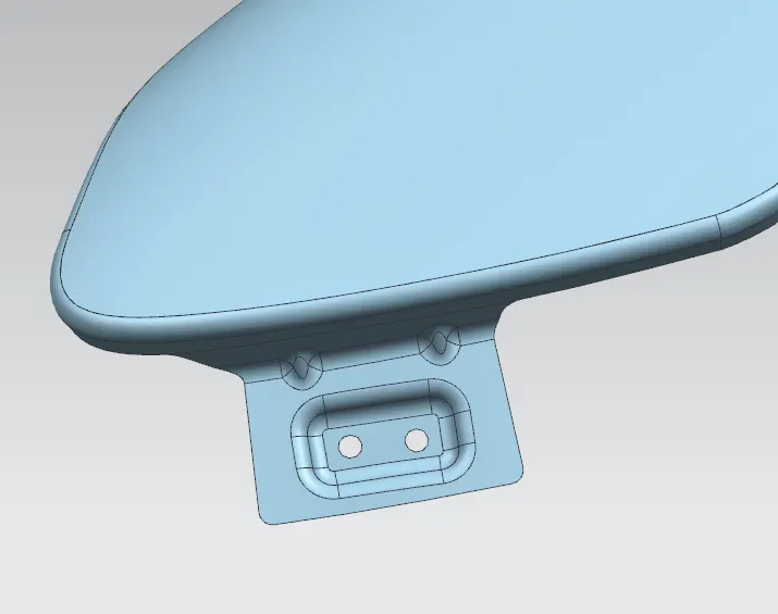
BAFFLE MOUNTING AREA :
Baffle mounting or also known as mudguard .
It protects the car engine compartment and also prevent any injuries to pedestrains and contain the motion of these particles.
They are mounted on the fender using a special type of locking clips which are made up of plastics .
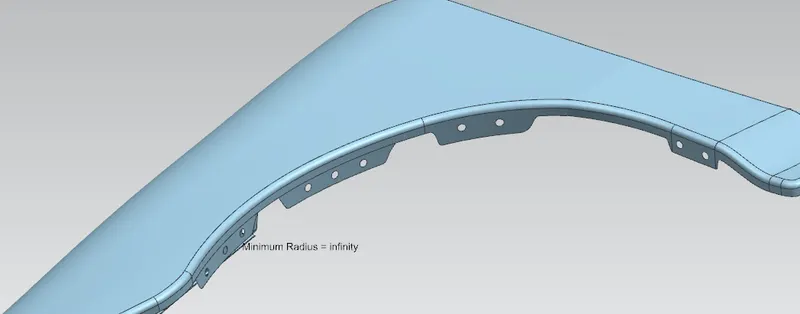
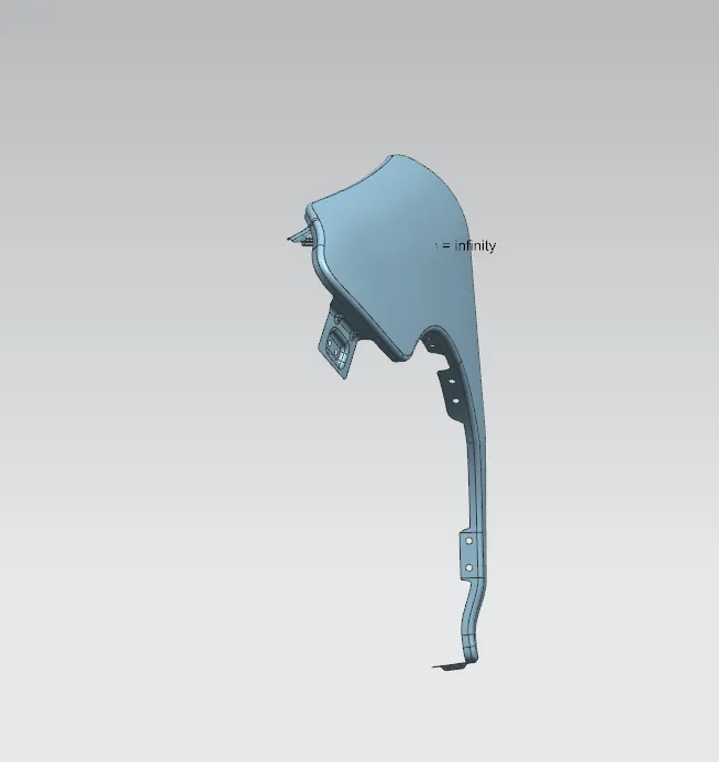
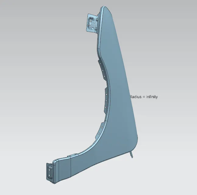
DIFFERENT VIEWS OF FENDER :
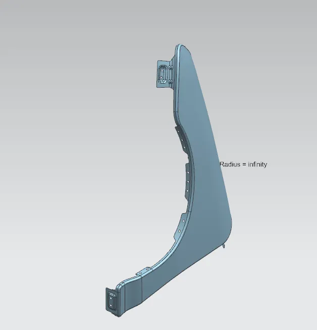
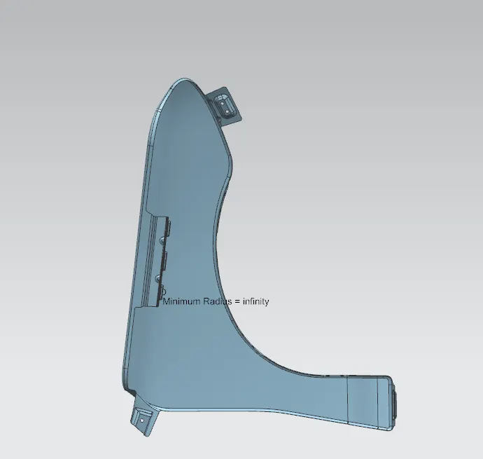
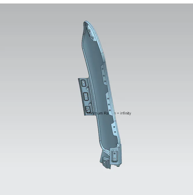
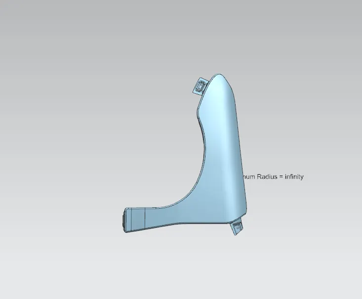
CONCLUSION :
Thus, i have completed the mouting of the front fender by using nx cad software .