Fender Design Challenge
AUTOMOTIVE
BIW DESIGN
FRONT FENDERS OF A CAR
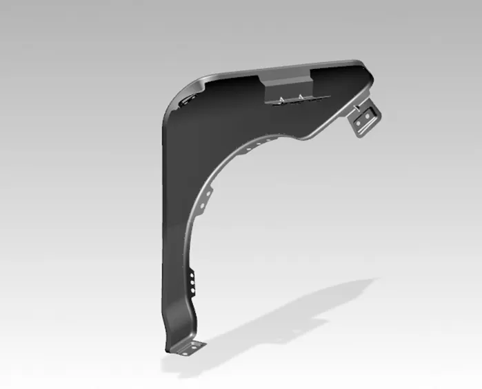
Automotive BIW Design using NX CAD11.0 | SWAROOP T
Fender is the American English term for the part of an automobile, motorcycle or other vehicle body that frames a wheel well (the fender underside). Its primary purpose is to prevent sand, mud, rocks, liquids, and other road spray from being thrown into the air by the rotating tire. Fenders are typically rigid. Sticky materials, such as mud, may adhere to the smooth outer tire surface, while smooth loose objects, such as stones, can become temporarily embedded in the tread grooves as the tire rolls over the ground. These materials can be ejected from the surface of the tire at high velocity as the tire imparts kinetic energy to the attached objects. For a vehicle moving forward, the top of the tire is rotating upward and forward, and can throw objects into the air, at other vehicles or pedestrians. In British English, the fender is called the wing (this may refer to either the front or rear fenders. However, in modern unibody vehicles, rear fenders may also be called quarter panels.) The equivalent component of a bicycle or motorcycle, or the "cycle wing" style of wing fitted to vintage cars, or over tires on lorries which is not integral with the bodywork, is called a mudguard in Britain, as it guards other road users – and in the case of a bicycle or motorcycle, the rider as well – from mud, and spray, thrown up by the wheels. In modern Indian and Sri Lankan English usage, the wing is called a mudguard.
Wheel Arch design criteria according to European Standards
While designing the fenders of a vehicle, engineers and designers must follow the specified design criteria of the respective country, which protects both car and pedestrians from unwanted particles such as mud, water stones etc. It also protects the car body itself from mud and other particles thrown away by the tyre while running. Design rules have been proposed by vehicle and road safety community. Below image briefly mentions the European standard for designing fenders.
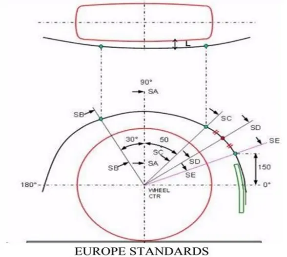
The minimum clearance (L) made by all the points (SB, SA, SC, SD & SE) must be 10mm or more.
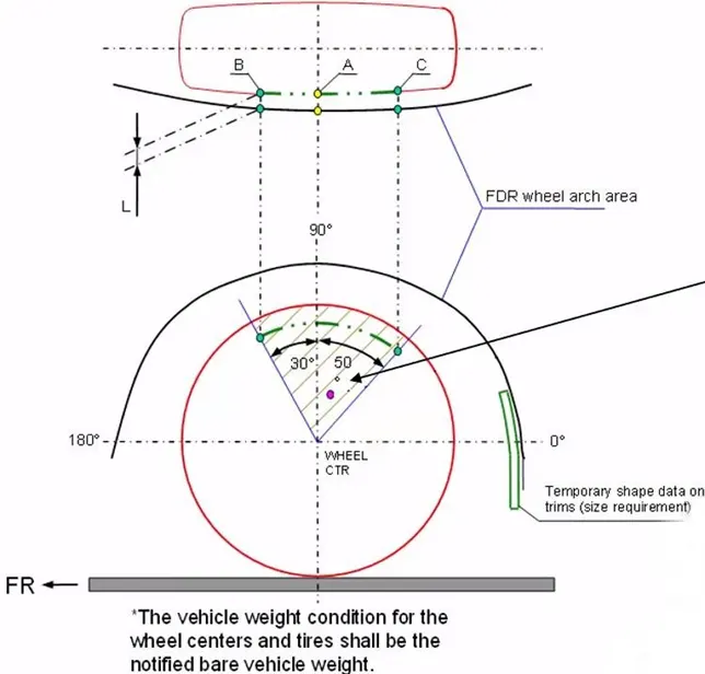
JAPANESE STANDARD
According to Japanese standards the minimum clearance must be 5mm and plotting of points are basically as shown in the diagram.
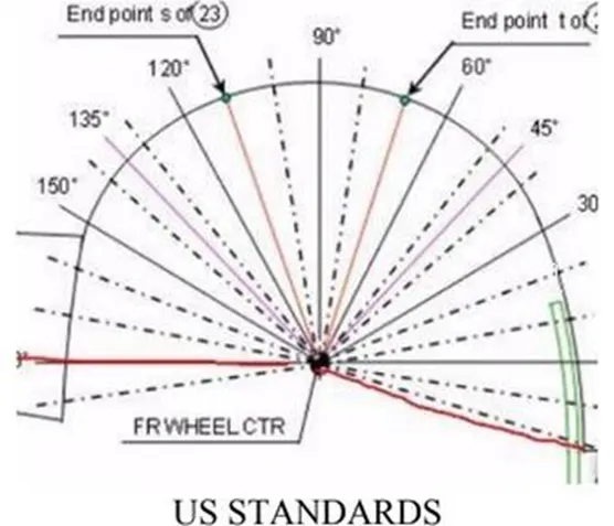
All values should be greater than 5mm in order to satisfy the regulations
If a car model is supplied in several countries following different regulations according to their roads, the design will be a common one suitable for all the
Types of fenders
- Full bumper type
- Half bumper type
above regulations instead of separate designs which cause more cost
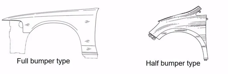
Now a days we mostly use half bumper type fenders, as the other one cause more wastage of blank material compared to half bumper type. Because, by slightly increasing the blank size we can produce two fenders at the same time if we are following half bumper type design.
Design Methodology
Here we have to design the front fender using the styling surface forwarded by styling team after analysing the wheel arch and drip area requirements following pedestrian safety. Master sections are also provided as shown below.
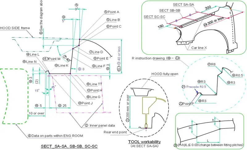
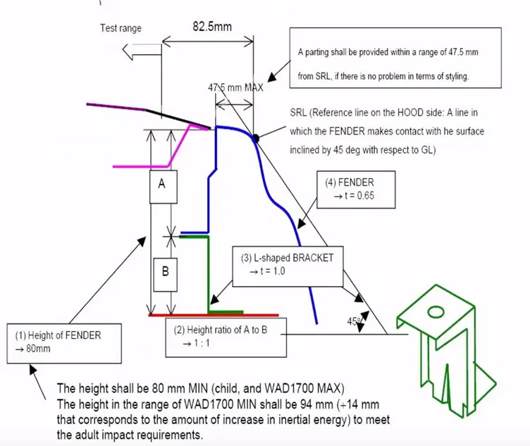
Following the master section and considering various factors such as accessibility of tools while assembling the fender into the engine compartment, spring back effect (usually if the depth more than 60mm) etc. we have to design the fender in a manufacturable, safer, and cost efficient manner.
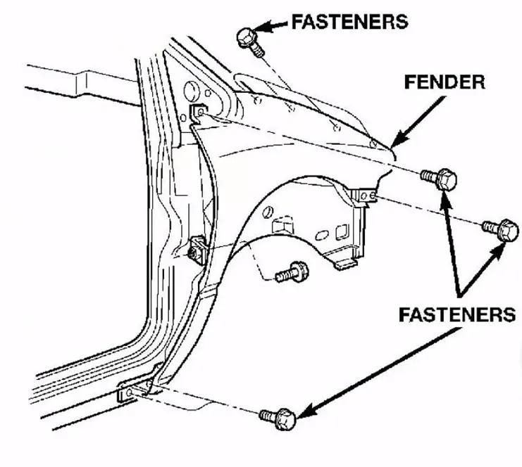
We have to design various mounts such as;
- A pillar mount
- Sill mount
- Bumper mount
- Flush mounts
- Drip area
Sufficient strength must be ensured by providing suitable embosses and beads following the engineering standards. Minimum fillet radius of 2.5 mm must be applied in order to ensure pedestrian safety as well as manufacturability and aesthetics.
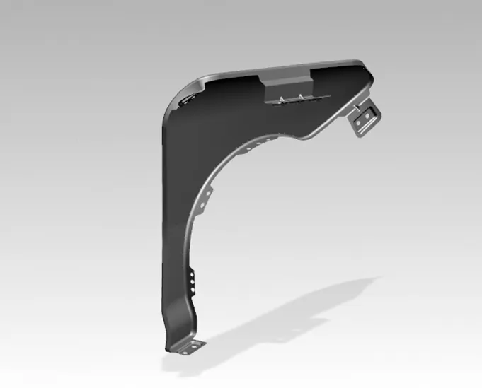
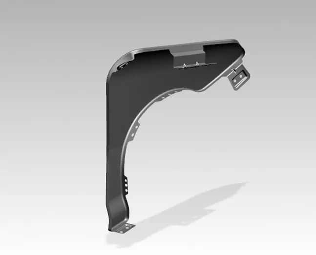
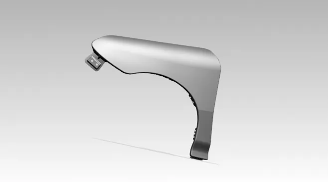
FINAL RESULT
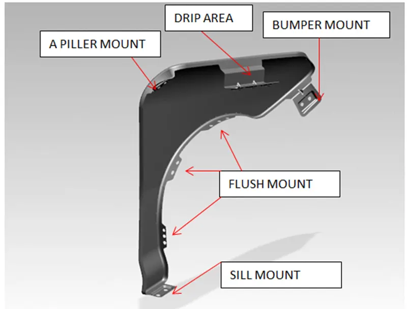
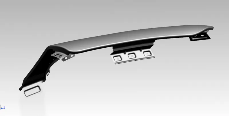
Front fender designed after safety as well as manufacturability considerations and with necessary assembly mounts using NX CAD 11.0
Conclusion
Thus using the styling surface received from styling team, front fenders of the car were successfully designed following the engineering principles. Next, this will be forwarded to CAE team for further analysis and will be modified if needed.
REPORT SUBMITTED BY: SWAROOP T (Design Engineer)