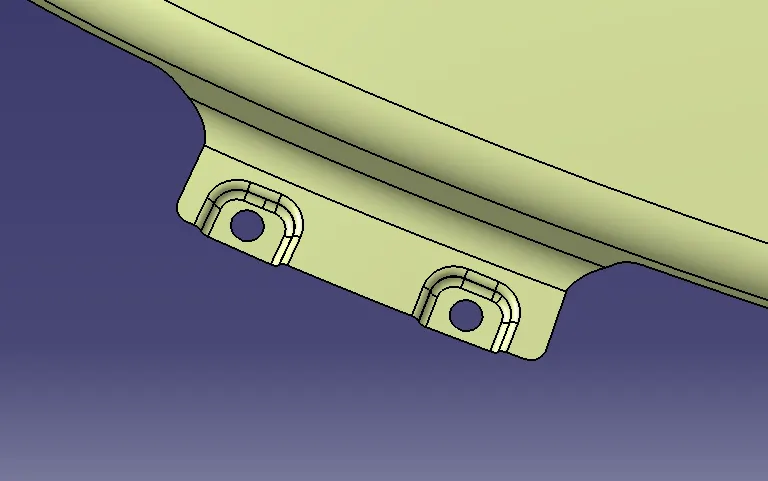
Fender Design Challenge
Objective:
To design drip area , sill mount , cowl mount, bumper mount and A pillar mount from given master section and according to engineering standards.
Answers:
Introduction
Fender is a part of an automobile that frames the wheel . A car has 4 fenders i.e 2 in the front and 2 at the back .
Primary function of a fender is to protect both passengers and pedestrians from materials like sand,rock,water,debris etc which are thrown away due to tire roation .
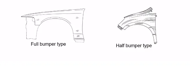
Fenders are mounted on 5 areas using fasteners .Each of these areas have certain Design considerations inorder to meet vehicle standards as well as meet manufacturability.
a)Drip
b)Sill
c) Cowl
d)A Pillar
e) Body .
General Fender requirements
1) Min height should be 80mm for WAD 1700MAX and 90(+14)mm for WAD 1700MIN condition for impact saftey .
2) If drip depth >60 mm , a base support bracket of equal height and 1mm thickness should be placed below for support .
3) Parting line should be provided within 47.5 mm from SRL .
4) Side Reference line should be given an angle of 45 degrees with ground.
5) Embosses should me made at all necessary areah which require additional strength
6) Minimum fillet value should be 3.75mm at all areas except emboss.
7) There should not be any sharp edges or corners
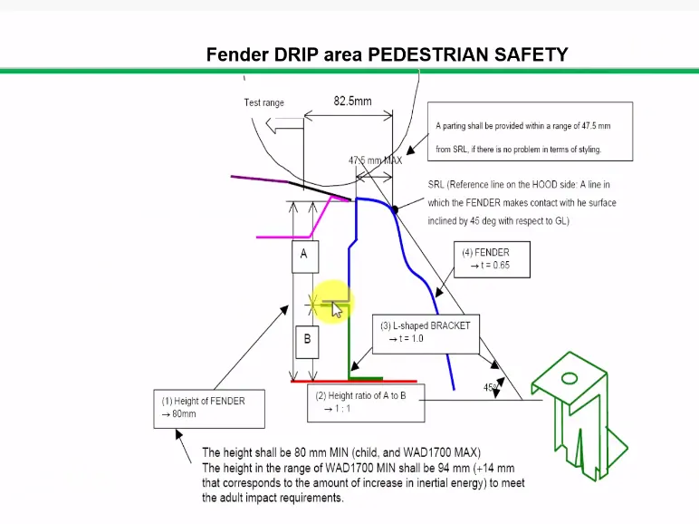
Engineering standards for designing Drip
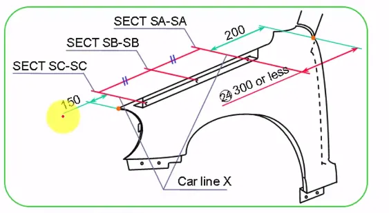
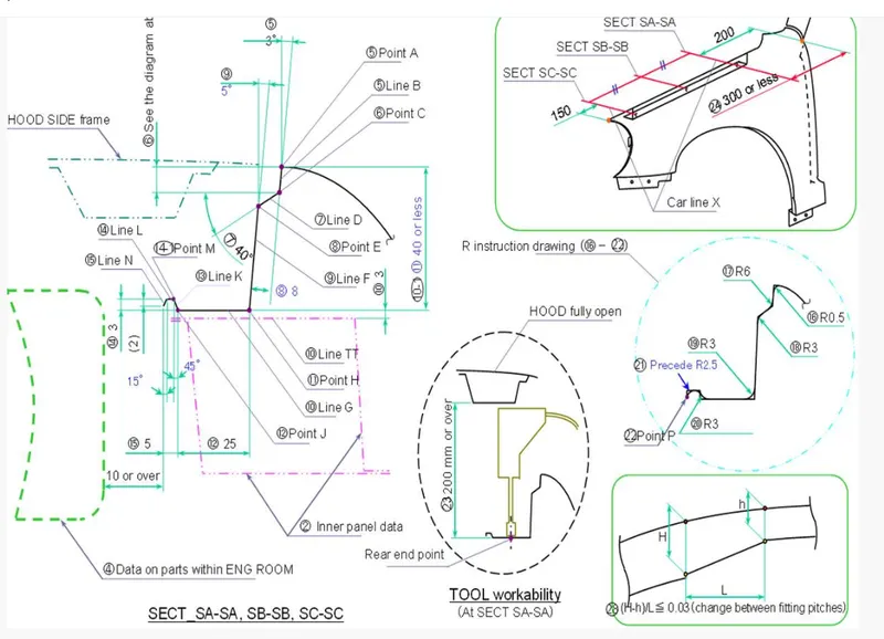
1)Mostly prefferd depth for 3 sections should be equal . If that criteria is not met, then depth should either increase or decrease from A to C . That is depth of A>B>C or A<B<C .
2)There should be adequate clearance of 200mm from front section of viper mounting area and 150mm from front section of fender
3) Max depth of drip area should be <40mm to avoid spring back effect and for ease of manufacturing .
4) For drip base flange , minimum draft of 3 degrees must be given to compensate for spring back and for modification if needed .
5) An offset of 8mm should be given for vertical flange for hiding the visibility from outside .
6) Clearance must be given to drip base area to ensure tool workability.
7) Fillets should be made at all corners for ensuring manufacturability and safety.
8) Embosses should be created at mounting points to improve strength .
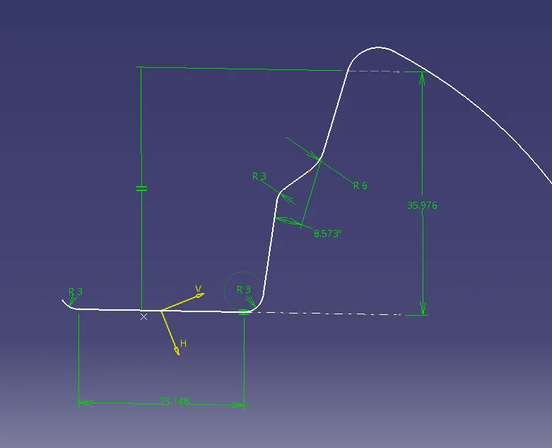
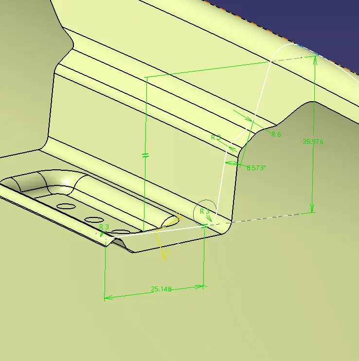
Given master section for drip area
Section sketch of drip area
Engineering standards for wheel arch area

L is the distance between end of wheel arch area on the fender and vertical line drawn frim outermost point of tire at various sections .
For Japanese standards L>5 at A,B and C
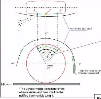
For European standards L>10 at all the sections i.e SA,SB,SC,SD and SE .
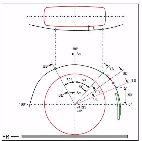
For US standards L>5 at all sections
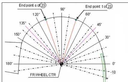
Mounting points at wheel arch
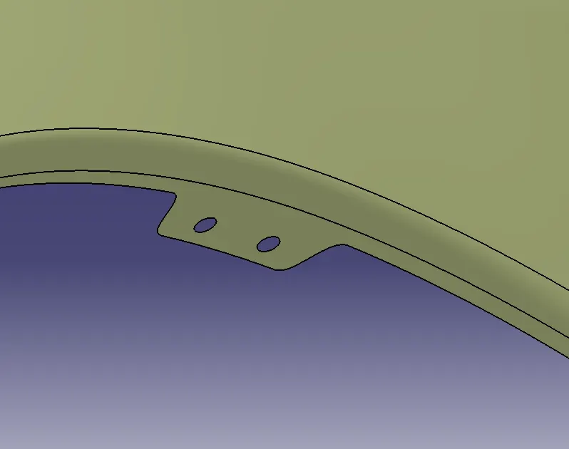
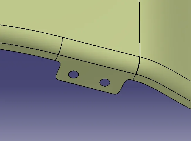
Mounting points at Sill
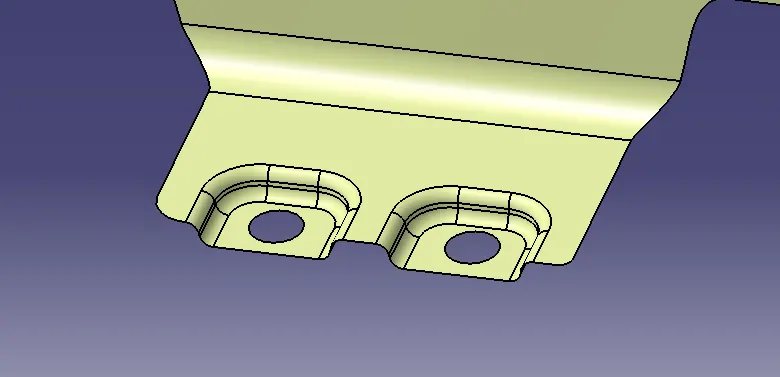
Mounting points at A pillars
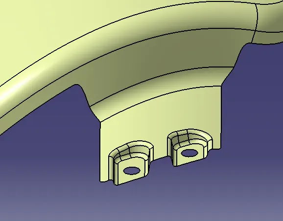
Mounting points at bumper section