Fender Design Challenge
FENDER DESIGN
AIM: - To design the fender according to the given Sketch, design parameters related to industry standards.
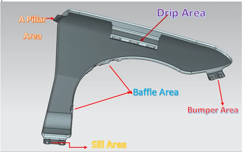
OBJECTIVE: - The main objective of this project is to learn the basic tools, commands, and Surface modeling of the Fender Design using Siemens NX CAD. To design a Fender mounting on the given model by using Master sketch by considering the safety and manufacturing feasibility for possible mounting region.
1. Design Drip Area
2. Design Sill Mount Area
3. Design Body Mount Area
4. Design Bumper Mount Region and A-pillar mount Region
INTRODUCTION: - A fender is a piece of a vehicle, cycle, or some other vehicle Its fundamental job is to prevent sand, mud, rocks, liquids, and other road sprinkles from being thrown into the air by the turning tire. In extra to fender various parts like internal mount, side, and cowl mounts that are joined with well nuts' help. They give satisfactory protection to the engine room portions and suspension, etc. In like manner, the fender keeps all the debris from the road from throwing into the air. Despite the fender, Fender skirts are given to give better protection.
Fender is the American English articulation for the piece of a vehicle, cruiser, or other vehicle body that traces a wheel well. Its essential job is to hinder sand, mud, rocks, liquids, and various roads shower from being thrown into the air by the turning tire. Fenders are customarily unbendable and can be hurt by contact with the road surface. Crude materials, similar to mud, may adhere to the smooth outside tire surface, while smooth free articles, similar to stones, can end up being unexpectedly embedded in the track grooves as the tire turns over the ground. These materials can be jump-started out from an external perspective of the tire at fast as the tire gives engine energy to the joined things. For a vehicle pushing ahead, the most noteworthy place of the tire is turning upward and progress and can throw Objects into the air at various vehicles or individuals by walking before the vehicle. A fender is a front outer side individual from a vehicle, which covers the wheel side. It has such innumerable little features with great and terrible occasions.
USES OF FENDER: -
- Get other vehicles or pedestrians on the road side dirty.
- Hurt pedestrians.
- Scratch the bodies of other vehicles.
- Cause minor, and even major damage to other vehicles.
- It is designed to provide resistance against wind, muds, and roadside partials.
- It is the sheet of metal covering of the car.
- Fender has a plastic part called Baffle or fender Liner which fits underside the fender to protect the metal from corrosion by stopping the flow of mud and water inside from different road conditions.
TYPES OF FENDERS: -
There are two main types of fenders-
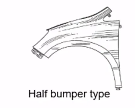
The Full Fender type: The full fender type is the standard sort of fender where more material use is observed. This sort is utilized in the old designs of vehicles where it manufactures the general weight and suitably lessens execution. The upkeep is besides modestly more because of more surface.
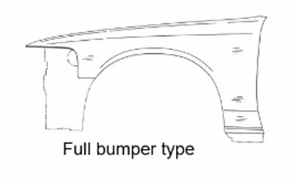
The Half Fender type: Half fender type is a forefront design where less material use is seen, so capability increments by decreasing the indisputable size and giving more presentation. The assistance in like way unassumingly low stood apart from the full guard type.
DESIGN PARAMETER
MOUNTINGS: -
PARTS DESCRIPTION: -
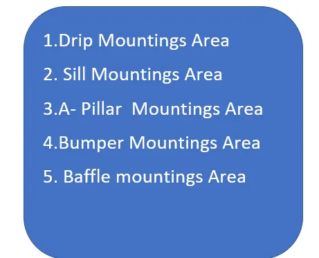
1.Drip Mountings Area
Primarily, the fundamental design of a fender incorporates developing the spilling area as it is a huge mounting region and requires certain characteristics that should qualify a fender design. Accepting it isn't true to form design, the spilling area would be recognizable from the opening between the hood and the fender. The overabundance mountings are covered by various parts.
Procedure:
- By utilizing the data in the master section gave the dribble mounting was made.
- The drip area would be recognizable from the opening between Hood and Fender.
- This mounting is attached to the engine compartment of the car.
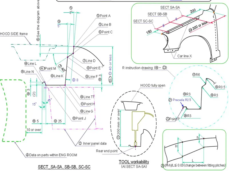
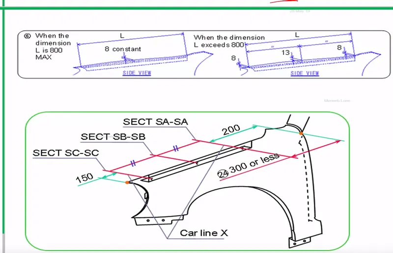
- A min 150mm distance is kept from the front side and a distance 300mm or less can be kept on the rear side.
- At that point, the excess undesirable parts were trimmed out.
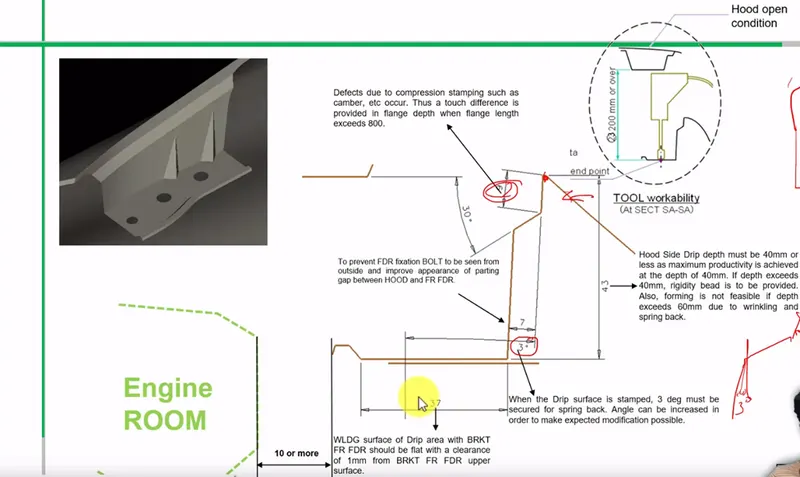
- This is to avoid the spring back during the manufacturing. the edge of the mounting should at least 10mm away from any nearby component in the engine.
- The drip area should be less than 40mm.
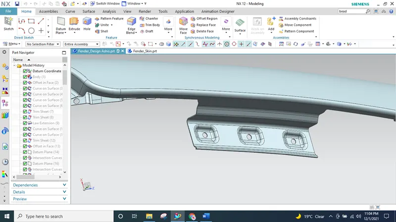
- The embosses that are created on the drip mounting should be flat with respect to the curvature.
-
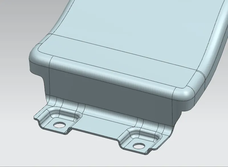
- Sill Mountings Area
An auto vehicle is essentially outfitted with wide openings for obliging doorways at the different sides of its body. Since the vehicle body encounters various kinds of distantly decided forces, for instance, vertical bends and longitudinal turns which act around the rotation of the vehicle body, a fundamental is that those sections of the vehicle body which include the entrance openings, especially the lower isolates, be outfitted with sufficient rigidity. This fundamental is generally met by using side edges which are only arranged at a lower right and a lower left piece of a vehicle body to connect the longitudinal method of the vehicle body. The side edges top in as working off people to ensure the vehicle body's inflexible idea around the doorway openings.
Procedure:
- For making the Sill Mounting the additional bits were trimmed
- At that point, the datum was made and the necessary sketch was drawn.
- The sill mounting is done by extension of sill area flange.
- After extension of flange holes were made for mountings.
- Embosses were created for the hole mounting points that provides more strength.
- A Pillar Mounting Area: -
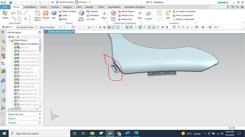
Pillars are vertical support on a vehicle. They have arranged around all the glass on a vehicle. They are critical for holding the glass set up and adding basic uprightness to a vehicle, primarily the housetop. The "A" pillar holds the windshield set up. "B" pillars head after the primary entrance. They by and large offer a critical fundamental framework for a vehicle's roof. As a general rule, they are bound to the body edge and wrap directly into the housetop. Dependent on the design, there may be different pieces joined to expand the reliability of the roof. They are moreover responsible for where an entrance's snare interfaces with the body. "C" pillars hold a vehicle's back window set up.
Procedure
- To begin with, the skin information given by the styling group should be removed.
- At that point, the external edge of the fender was counterbalanced inwards to a specific length. At that point, by utilizing the bend on surface command the undesirable segments were trimmed out utilizing the trim sheet.
- By utilizing the law extension, the A-Pillar was expanded and trimmed on the sides to get a level edge.
- For making embosses which was utilized to mount the fender with the A-Pillar a datum plane was made.
- At that point, the necessary sketch was drawn on the datum plane.
- At that point, the necessary mixes were added utilizing face blend and edge blend.
4.Bumper Mounting Area: -
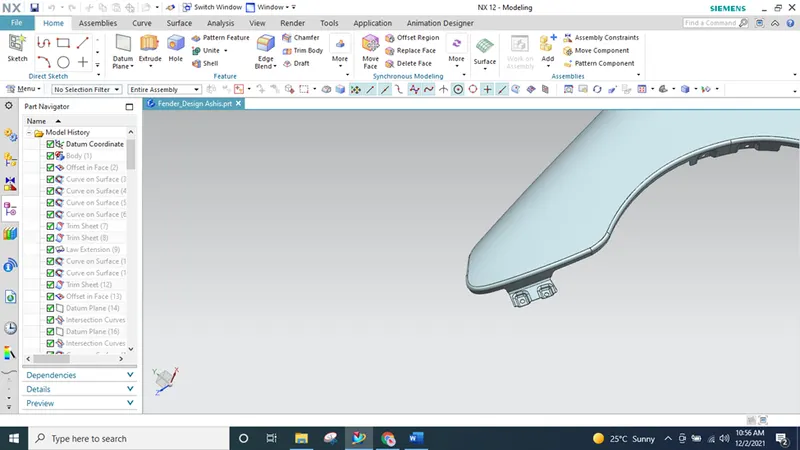
A guard is a construction appended to or incorporated with the front and backsides of a car, to ingest sway in a minor impact, in a perfect world limiting fix costs. Along these lines, the guard mounting area includes the excess piece of the fender that covers the sprinkle locale in that of a half fender type. Guards are progressively being designed to alleviate injury to people on foot struck via vehicles, for example, using guard covers made of adaptable materials. Front guards, particularly, have been brought down and made of gentler materials, like froths and crushable plastics, to diminish the seriousness of effect on legs.
Procedure
- The undesirable bits were trimmed off utilizing Curve on surface and Trim surface command.
- At that point for making a level surfaced Emboss a datum plane was made and that point, the necessary sketch drawn on the datum plane and the required decorate was made.
- The openings were trimmed by utilizing a trim sheet after making embosses. Trim the 5mm hole.
- At last, the necessary face blend and edge blend were applied.
5.Baffle Mounting Area: -
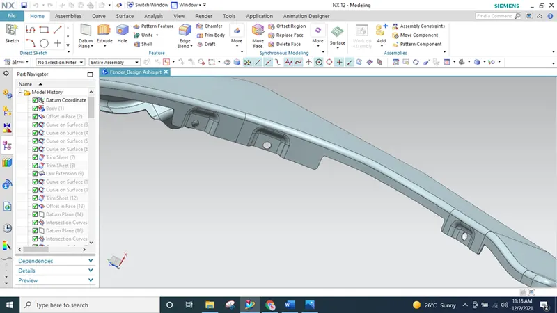
To stop all the debris going into the engine room and various sections like suspension joints and so on, a sprinkle defender mounting part is being set. The Baffle mounting area requires just to hold the baffle defender mounting the openings are being given in the design. For certain automobiles, notwithstanding the fender, fender skirts, and guards are submitted in solicitation to give better protection. The design isn't exceptionally connected with baffle mounting. Just to offer openings to the hooks set up.
procedure
- The baffle mounting was designed to fit a baffle mounting on it which helps the motor compartment to shield it from the flotsam and jetsam that going into it while driving.
- For making the openings a datum plane was made on every one of the three mountings and projected onto the surface.
- The embosses are made on datum plane and applied edge blend and face blend and trimmed off the 5mm hole
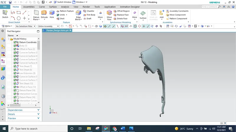
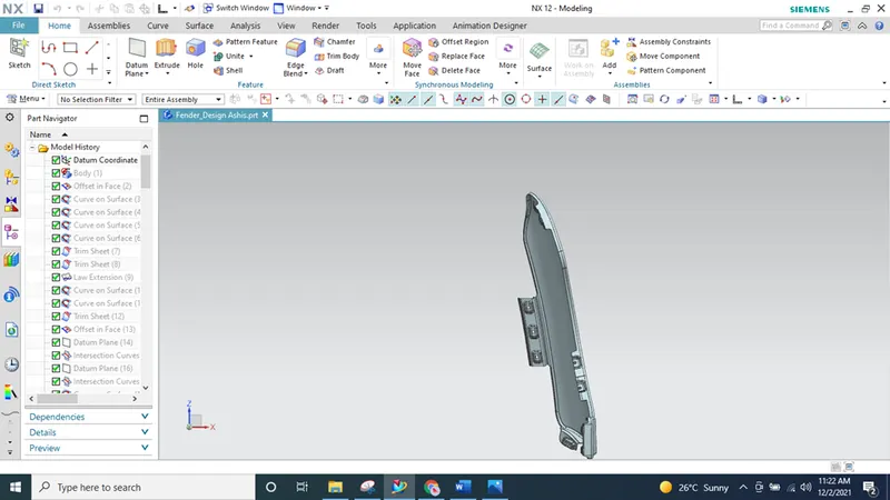
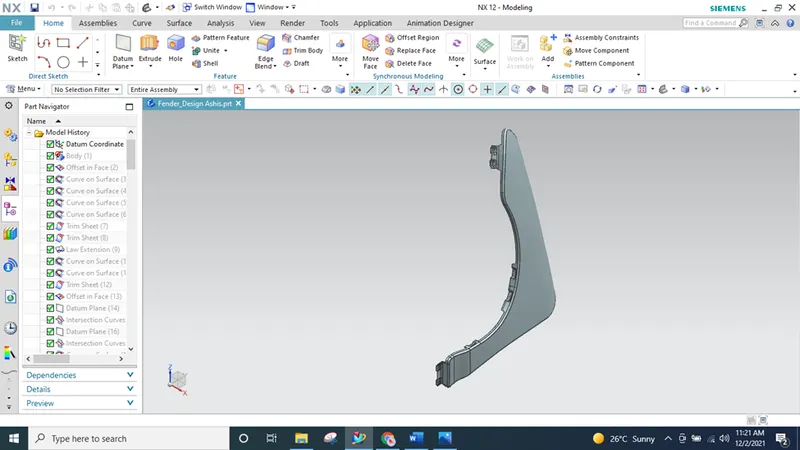
Design View
Top View
Front View
Isometric View
Conclusion:
We designed the Front Fender in NX application with proper mountings by using the Master Sketch and Design Parameters.