Fender Design Challenge
AUTOMOTIVE FRONT FENDER DESIGN
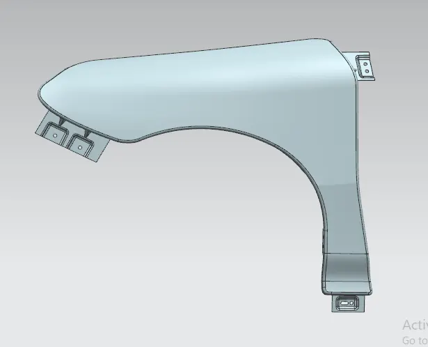
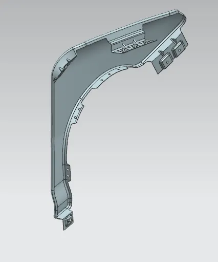
Introduction: Here I'm going to generate the sheet metal part of a front fender from the given class A skin data. The design procedure of a fender mainly focussed on the mounting of other sheet metal components. The fender part will be an indipendent part which have extensions and screw holes provided to fit into the near elements. Various types of mounting portions can be included into the areas comes inward of the carbody. All features must be installed in a way that they cannot be visible when directly looking from outside.
Fender part must be stiff and stable. When the vehicle is in moving, all the debris mud or sand particles will thrown into the inside regions of wheel arch. fender should be strong to prevent vibrations and chipping. Also as well as the other important parts in the front side of a car, a fender also included in the crash analysis.
In this project, we will be making some of the important mounting features on to a surface part of fender.
Software used: SIEMENS NX 12.0
Various design considerations for fender:
- Functional requirements
- Important regulations
- drip area
- Baffle and ORVM mount area
- Frontal crash regulation requirements
- Gap and flushness requirements
Design methodology:
Given class A skin data:
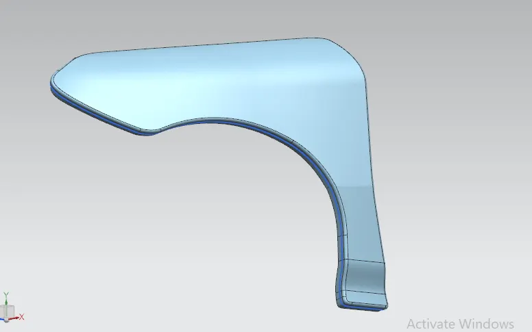
First step is to analyze the skin data for surface continuities and overall smoothness of the skin data. Any missing areas or opened sections needs to be filled according to the requirements provided.
As per the mounting datas provided, we have to mark the regions for all mounting features and trim the extends.
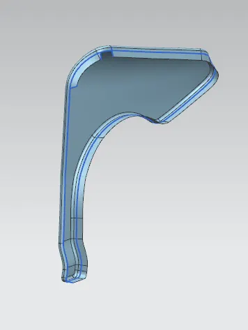
The Most important mounting features included in this project are:
- Drip
- bumper mount
- sill mount
- A pillar mount or body mount
- wheel cover mount
Constructional data:
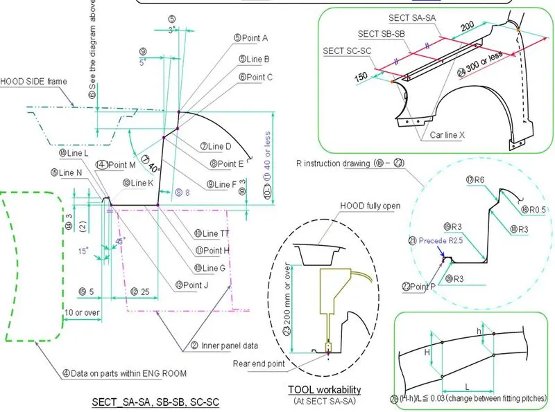
DRIP:-
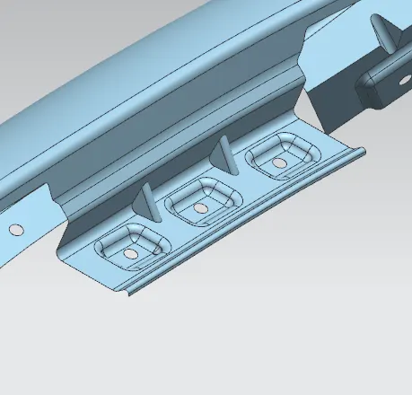
Drip is the extension which comes into the engine bay. It is the main mounting feature which covers a large area of the fender at top portion. Drip part have some special arrangement designed by considering the workability of the tools. The mounting points in drip area comes inside the engine bay. It is important to block the visibility of these parts to outside.
The length of the drip region is decided by the length criterias. It's length comes at 150mm apart from the bumper mounting edge and 200mm apart from the A pillar mounting side.
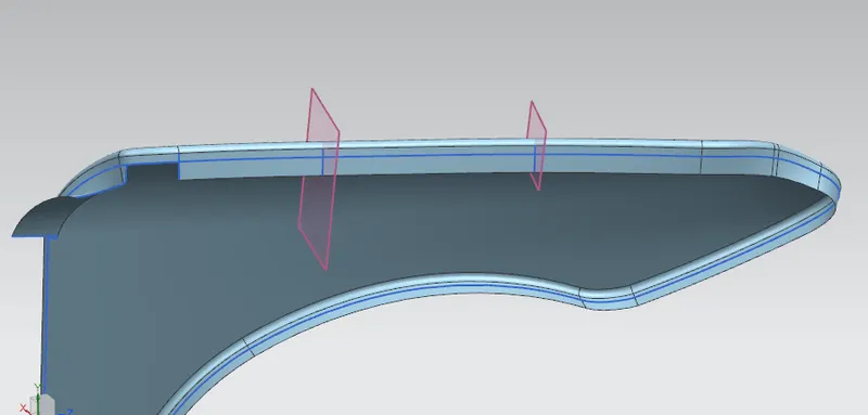
The drip part needs to be constructed using law extensions according to the design datas:
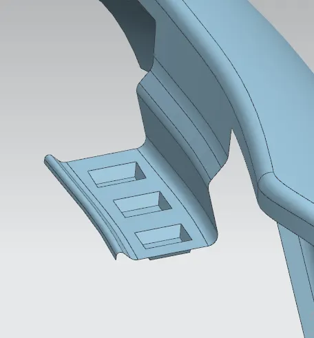
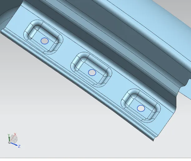
For screw holes, we provide embosses at a depth of 3.5 mm. mounting points needs a bit extended from the surfacefor proper alignment.
Since there are some corners and sharp edges, there will be higher chance for stress conentration regions. We provide stiffeners(Dart) to strengthen the corners.
Bumper mounting:
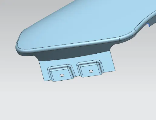
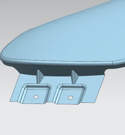
It comes at the front portion fender. connecting to car bumper. Again, the specifications will be different for all vehicle manufacturers, but the commonly used one is shown here.
Sill mount:
Sill mounting region is made at lower portion of the bumper. For the mounting application, we provide a special type of screw hole:
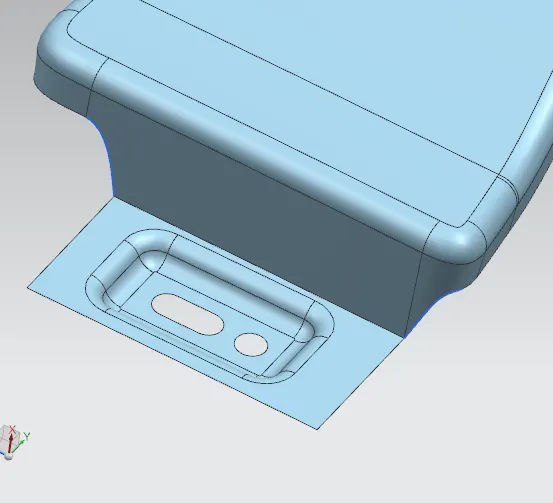
the will be a hole and a slot nearby, One hole will be exactly at the required position and the other can be mounted anywhere in the slot provided. It is a specification for GD&T for preventing the errors and improve flexibility of design.
A pillar mounting or body mount:
The region connecting to main body panel or A pillar. Extensions will be according to the specifications provided.
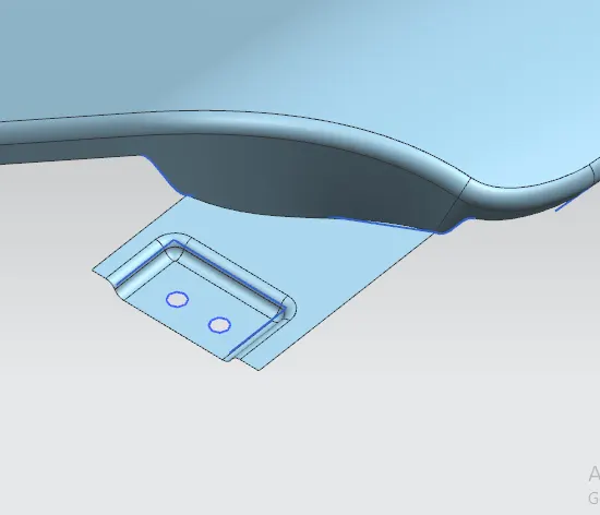
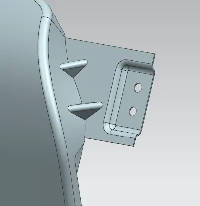
Wheel arch mounting area:
For wheel arch, we only provide screw holes, since the wheel arch part will have embosses created on it.
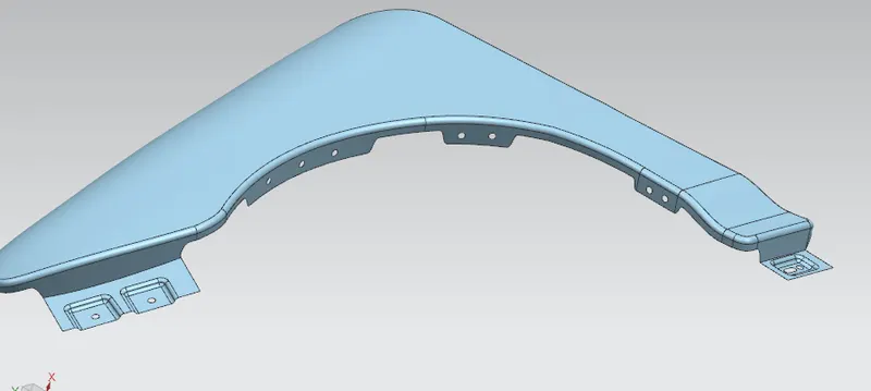
Final part: