Fender Design Challenge
THE FENDER ASSEMBLY
the desing of the fender for the cars having the different approarch there are useing the different parameters as showing
CONTENTS ARE
- introductionsc
- fuctional requriment and types
- assembly flow
- desing approach
- desing parameters
- cad approach
- conclusion
IN fender desing the main thing is to find is NVH =NOISE VIBRATION HARDNESS
there are
- air borne nvh
- structure borne nvh
science of managing the vibration frequences in automobile desing is called the nvh in automobile
introduction
in this introduction we are learing about the desing of fendear assembly .in this feander assembly we used the few cad fuctions by the use of the cad fuction we get the good result of fender assembly desin fust we are stated from the fender skin data.the data which is used for the desing of the fender.with the help of the fender desing video wich is used to fender assembly desing.
the fender is used in car mount in front of the wes dhe men working of fender is ;
- fender the part of a vehicle that cover the wheel and its well its primery purpose is to stop the dirt water ar sludge from being thrown around by the wheel its often also calld mudguard given its purpose ther are to type of fenders
- full fender
- haif of fender
these are the fender assenbly desing,there are rhe few cad fuctions are used in the desing of the fender assembly. the cad fuctions are
CAD APPROACH
- EXTRACT BODY
- PARAMETRICE MODEL
- THICKAN
- CREATE LAYERS
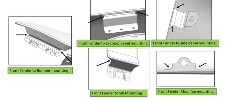
- MOUNTING LOCATIONS OF FENDER
- extract body from the input panel .design is carried out in extracted body.intention is not to modify the input panel.
- all features are easily editable for modification.make all sketeches fully constarined.
- cstegcrize the features move them by creating appropriate layers,
- create master section section sb offset curve on face and use this as swepp trajectory sweep the section curve on surface for corner relife holes and pattem sew with main panel,
DRIP AREA
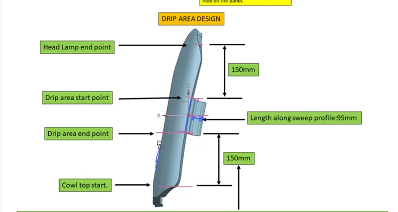
- it is the area through which fender is attached to engine housing through fasteners.
- there should some consideration to desing the drip area of fender.
- from back side of front fender,there will be 200mm clearance for coml[wiper motor]mounting area.
- from front side of front fender ,there will be 150mm clearance for head lamp housing unit.
- remaining area we can use to desing a drip area.
- height of fender can be minimum 80mm for child and adult impact.
- parting will minimum 5 not more than 50mm from SRL
- drip area will not reach engine assmbly due to restriction of 40mm linght, so there will some L-shaped bracket to connect with it
ASSMEBLY FLOW
the assembly flow of the fender desing is show in the help videos, we need to flow the steps to create the assembly of the fender.first we are making the drip arer whichnis the main part of the fender assembly.during the create the fender few dimensions we need to flow and making of holes ,we used the few tools for appoarch of the fender desing .
CONCLUSION
- in this project report of front fender panel
- i have gathered all the parameters of fender and presented to you as 6-step approach
- the objective of the project is achieved however as per the project scope and input availability the items highlighted in red in the flow chart 2 are assumed to be all considered in design and are okay