Fender Design Challenge
AIM:
The main objective of this project to design the front fender of the car by following the master section data on the provided fender skin data. The design should meet the minimum design requirement .
INTRODUCTION TO FENDER:
- Fender is a part of a car which is used to protect the sides of the engine compartment.
- The fender is situated above the wheel of the car so that it can protect the side parts of the car and other vehicle which is moving nearby since the chips and debris thrown from the wheel in movement could cause damage.
- The fender also reduces the pedestrian injury when there is a pedestrian vehicle collision and prevent throwing up of debris to nearby vehicles.
- Usually the front fender is designed seperately,the rear fender come along with the body structure.
- Pedestrian safety is also considered while designing wheel arch in fender since the debris in wheel should'nt hit them in the motion of the car.
- There are drip area mounting,sill mounting,A pillar mounting,bumper mounting in the fender.
fender designing requirements:
- Drip area
- wheel arch
- Baffle and ORVM mount area
- frontal crash regulation
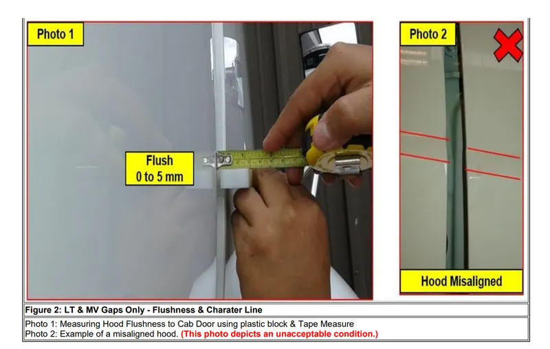
- gap and flushness
1.DRIP AREA:
The drip area is the place where the fender is attached to the engine room.It is essential to take it as first factor for consideration.The fender is attached to the engine housing by fasteners.This is called drip mounting.
The guidelines for positioning of drip area is given in the following image:
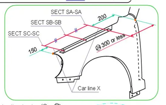
The clearance from the rear side is 200mm ,it is meant for wiper motor in the cowl.
The clearance from the front side is 150mm ,it is for head lamp housing. The requisite for designing the drip area is given in the master section.
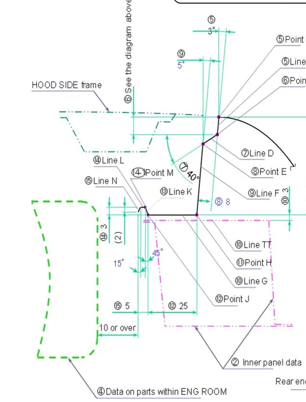
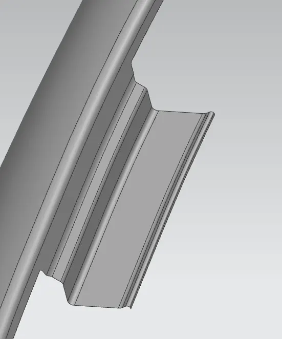
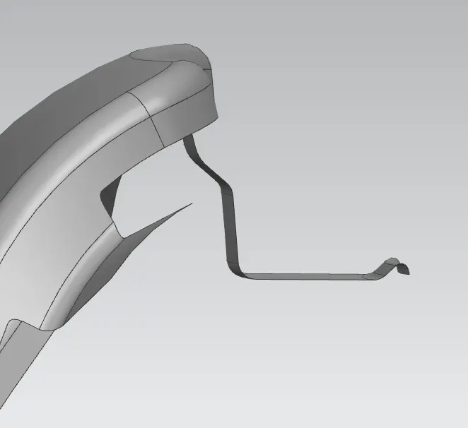
Drip area is designed in NX CAD as per the above image
POINTS TO PONDER WHILE DESIGNING:
- The problem that may arise in drip area is the flange that connects the mounting drip area and the fender is long enough to cause vibration when the vehicle is in motion.
- To overcome this we do a bead or dart operation in the drip area.
- The first flange from the fender start point would be of 9mm with draft angle of 3 deg this makes the part easier to produce for the production unit.
- The second flange of angle 40 deg ,length 7-8 mm is given to hide the view of internal non aesthetic parts like fastener, welding etc., from customer's eyepoint.
- The drip area where the fasteners are mounted should be 35-40 mm so it will be easy for the tool to work on it when the hood is opened.
- The depth of the fender should be of 40-60 mm,if the depth exceeds 40 mm bead should be provided when the design is not followed(exceeding of 60mm) it may cause the part to move back and fro called SPRING BACK EFFECT.
- Side reference length( A line in which the fender makes contact with hood by inclination of 45 deg) should be below 50 mm .
2.WHEEL ARCH:
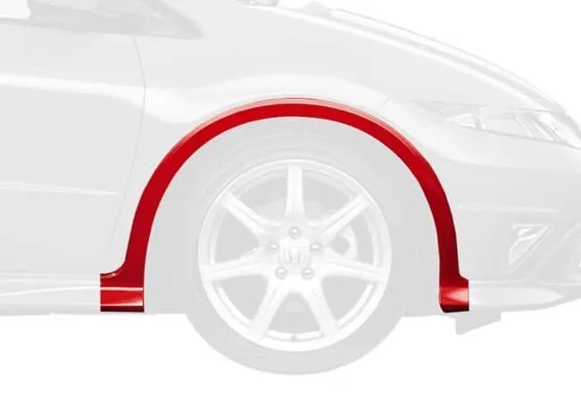
The wheel of the car will be present undeneath the wheel arch of fender .It protects the engine parts from hitting by stones and other debris which is in the groove of the tire when the vehicle is in the position.
The wheel should be inside the fender in the front view of the car.The length varies from region to region according to their road standards.The following image shows the wheel arch of the full bumper type fender.
3.BAFFLE AND ORVM:
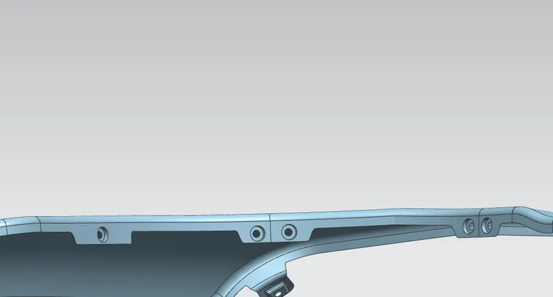
The baffle is a rubber material which prevents the internal parts from mud,water and other debris.
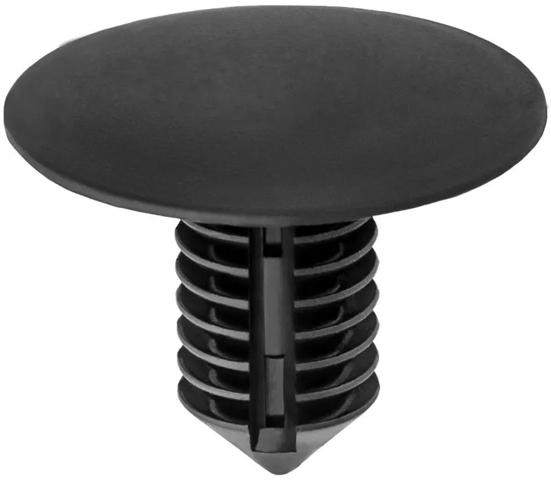
The baffle is usually attached to the fender using push clips .It is mounted on the wheel arch area.The following image shows the designed baffle mounting in NX CAD.
The push clip used to attach the baffle with the fender mounting which is shown below.
ORVM - It is outside rear view mirror.In some car models the ORVM is mounted on the fender.Now -a - days it is situated near the a pillar mounting.While designing measures to be taken when the ORVM is mounted on the fender.
4.FRONTAL CRASH REGULATION:
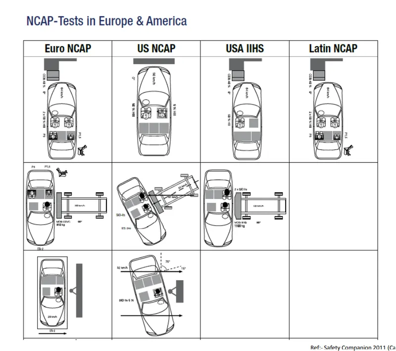
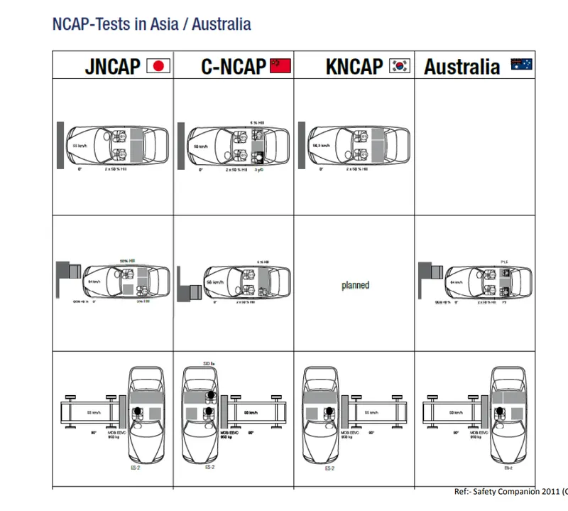
The crash is the collision of vehicle violently with an obstacle or another vehicle which may cause injuries to the passenger and the pedestrian.There are various organizations to ensure the peoples safety by assessing the car(EuroNCAP,US NCAP,US IIHS,Global NCAP etc.,).
The process is - NCAP = New Car Assessment Program
The strength of the front fender is analysed using the frontal crash analysis with the offset like 25% or 40%.
The crash analysis is done with dummies to replace the passenger. The following image crash assessment of the car according to various regulations.
PHYSICS OF CRASH:
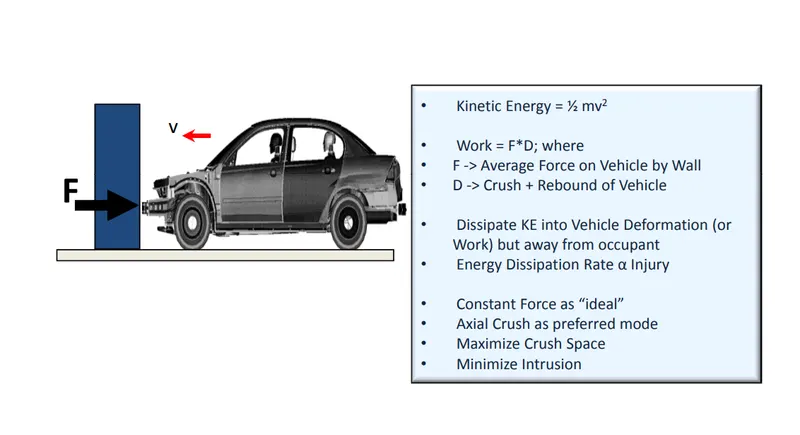
FRONTAL IMPACT TEST:
5.GAP AND FLUSHNESS REQUIREMENT:
There are certain requirements that a automobile industry should make a concern in gap and flushness of the car.
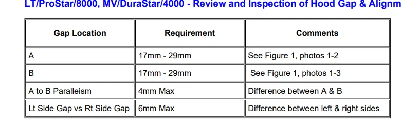
the position are,
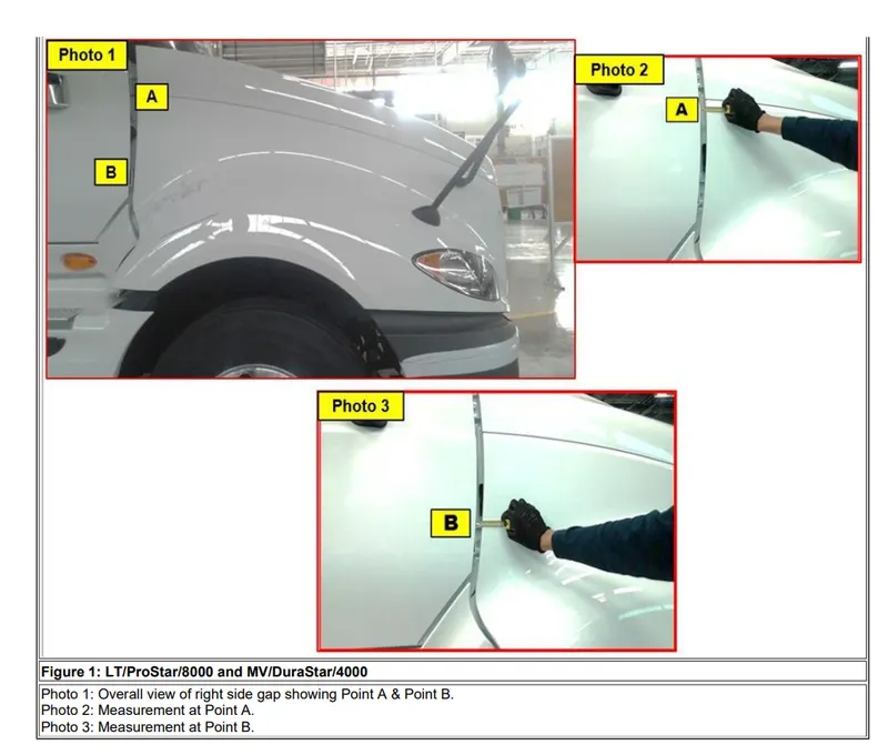
flushness measurement,
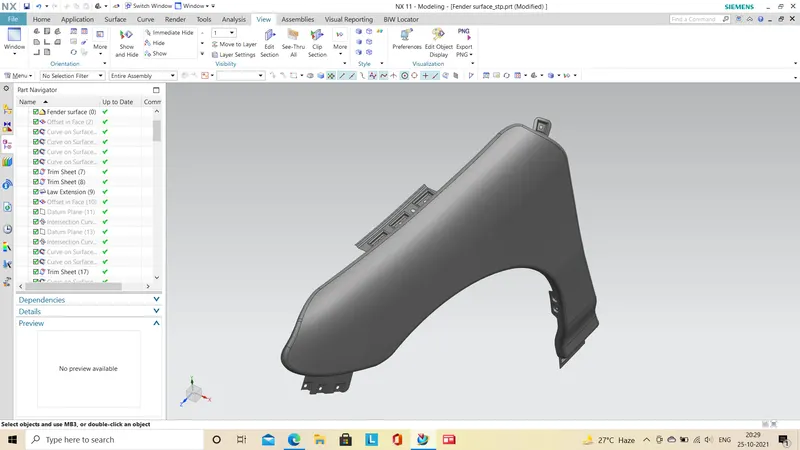
IMAGES OF DESIGNED FENDER:
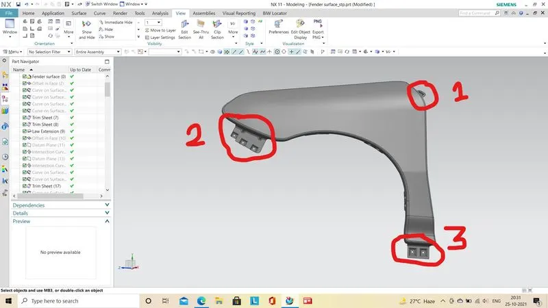
1.A pillar mounting
2.bumper mounting
3.Sill mounting
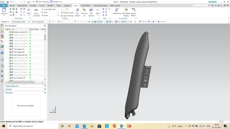
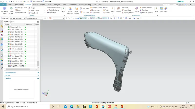
Thickening of the sheet boddy is to be done after completing all mounting features in the body.you may use blend coener to avoid sharp edges.
CONCLUSION:
The designing of front fender of the car is completed using the NXCAD by following the master data provided.It meets the design requirement for the fender for the safety regulations.
REFERENCES:
MC-10154136-9999.pdf (nhtsa.gov)
Microsoft PowerPoint - 11-Crash_Safety_practices (iitd.ac.in)