Fender Design Challenge
DESIGN OF FENDER USING NX
OBJECTIVE: The main objective of this challenge or project is to develop a fender and its mountings from the skin data provided and to know more about drip mounting, sill mounting, A pillar mounting etc.
Here we use NX software for our application.
INTRODUCTION
the Siemens NX is also known as Uni graphics NX is an advanced high-end CAD /CAM/ CAE software package originally developed by UGS corporation, but since 2007 it is owned by Siemens PLM software. it is used for tasks such as design, engineering analysis and manufacturing finished design by using included machining module.
NX11 introduces capabilities for convergent modelling, rapid manufacturing, improved annotations, drafting and documentation and rendering. active workspace in NX11 is built around these items to provide seamless access to PLM capabilities right within NX
BODY IN WHITE (BIW)
Body in white (BIW) is the stage of automobile manufacturing in which car body’s frame has been joined together, that is before painting and before the motor, chassis, sub-assemblies, or trim (glass, door, locks, handles, seats, upholstery, electronics, etc.) have been integrated into the structure. The assembly involves different techniques such as welding (spot, MIG/MAG), riveting, clinching, bonding, and last brazing.
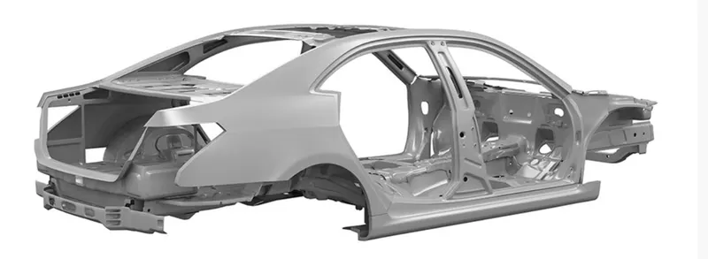
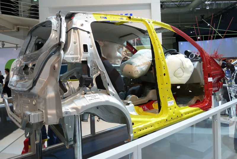
The below image shows us the Body in white, partially outfitted to highlight the safety system fitted to the vehicle.
FENDER
Fender is the American English term for the part of an automobile, motorcycle or other vehicle body that frames a wheel well (the fender underside). Its primary purpose is to prevent sand, mud, rocks, liquids, and other road spray from being thrown into the air by the rotating tire.
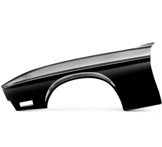
PURPOSE OF USING A FENDER:
Sticky materials, such as mud, may adhere to the smooth outer tire surface, while smooth loose objects, such as stones, can become temporarily embedded in the tread grooves as the tire rolls over the ground. These materials can be ejected from the surface of the tire at high velocity as the tire imparts kinetic energy to the attached objects. For a vehicle moving forward, the top of the tire is rotating upward and forward and can throw objects into the air at other vehicles or pedestrians in front of the vehicle, so to avoid this we must use a fender.
TYPES OF FENDERS:
There are basically two types of fenders in the market
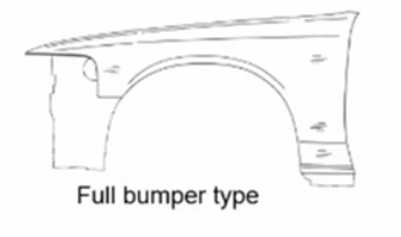
- Full bumper type:
Now a days these full bumper type fenders are becoming very rare because of their weight and the wastage of material while manufacturing them which increases the overall cost of the vehicle. And they will spoil the aesthetic looks of the vehicle. Hence in modern days these types of fenders are not using.
- Half bumper type:
These are the type of fenders which are used very often n the modern-day cars. These are light in weight and east to install them in the vehicle. This type of fenders reduces the wastage of material or blank to a maximum extent and this also enables us to mount plastic components which absorbs the shocks and vibrations better than full bumper type, so that improves the vehicle in NVH performance. So, this type of fenders also improves the aesthetic looks of the vehicle. Hence all the industries are preferring this kind of fenders.
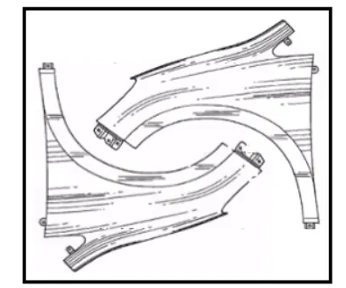
DIFFERENCE BETWEEN A FENDER AND A BUMPER
The bumper is installed on the front and rear side of a vehicle. Its main function is to absorb the impact upon collision, minimizing the damage to the main body.

The bumper is often moulded contoured plastic. It spreads horizontally across the front and back of an automobile that protects it from the minor front and rear collisions or “bumps”.
While the fender is the curved metal guard that arcs over the tyres.
Its primary purpose is to prevent sand, mud, rocks, liquids, and other roads spray from being thrown into the air by the rotating tyre.
DESIGN CONSIDERATIONS
- The thickness of the fender is to be 0.75 mm
- The drip area mounting design should be designed by following the master section provided in the challenge itself
- All other mountings should be designed in such a way that they must satisfy the design and manufacturing consideration
- Make all the corners and edges smooth by trimming or blending the surface.
- Try to get smooth surface.
FEATURES USED IN NX
OFFSET CURVE ON FACE: The offset curve on face command in siemens NX is used to create offset curves on one or more faces from connected edges or curves on the surface. The offset curves can be associative or non-associative, and lie at a specified distance from an existing curve or edge section. The curves are created on the face, and are measured along face sections normal to the original curves.
|
CURVE ON SURFACE: The curve on surface feature in siemens NX is used to draw splines in the surface. for this we need to select the surface and we have to specify the points on the selected surface.
BRIDGE CURVE: The bridge curve command in siemens NX is used to create, shape, and constrain bridge curves between curves, points, surfaces, or surface edges. You can also use this command to create symmetric bridge curves across a datum plane.
INTERSECTION CURVE: The Intersection Curve command in Siemens NX is used to create intersection curves between two sets of objects. Intersection Curves are generated between two sets of faces or planes.
TRIM SHEET: The trim sheet feature in siemens NX is used to trim off a portion of a sheet body using curves, datum planes, or faces. we can modify or create new sheet.
SKETCH: NX sketch anticipates what you are going draw or design. it identifies geomentric relations for you with the surrounding geomentry. NX sketch works seamlessly with data reardless of the source. this feature is at the top left corner of the screen when you open the sheet metal domain in the NX software.
LAW EXTENSION: The law extenssion feature in Siemens NX is used to extend an existing surface or sheet based on the laws for distance and the angle of the extension. Law Extension creates flanges or extensions when a particular direction is important or when it is necessary to reference the existing face. For example, in die design or mold design, draft direction plays an important role in creating parting surfaces.
FACE BLEND: The face blend feature in Siemens NX is used to add tangent blend faces between two or three sets of faces. The cross section of the blend can be circular, conic, or law controlled
EDGE BLEND: The edge blend feature in Siemens NX is used to create a blend between two sharp faces.
PROJECT CURVE: The project curve feature in Siemens NX is used to project curves, edges, or points that are external to the sketch, onto the sketch along the normal of the sketch plane.
EMBOSS: The emboss feature in Siemens NX is used to create embossed faces. the purpose using emboss command is to uncrease the stifness and strenght of the body.
DART: The dart feature in Siemens NX is used to add a dart feature along the intersection curve of two sets of faces. the dart is used on the the large faces which creates the vibrations and noises while the vehicle is moving. this dart increases the stability of the lenghty part so that vibrations and noises are reduced to maximum extent.
SEW: The sew feature in siemens NX is used to sew or combine the two surfaces into a single surface. to sew the bodies they must not have any gaps more than the specified tolerance value.
THICKEN: The thicken feature in siemens NX is used to offset one or more connected faces or sheets into a solid body. Thickening occurs by offsetting the selected faces along their face normals, and then creating sidewalls.
MOUNTINGS OF A FENDER
There are basically five types of mountings on a fender, they are
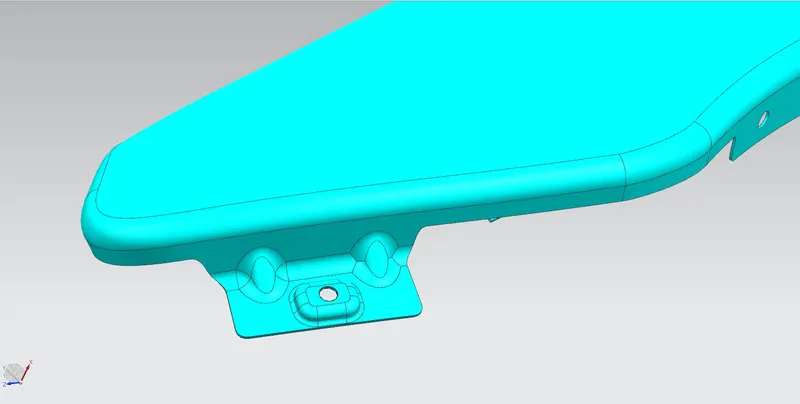
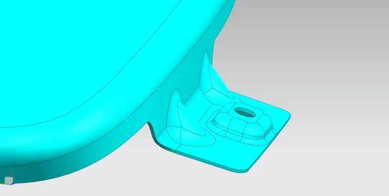
1.BODY MOUNT
1.To creare a body mount first create a law extenssion
2.create abridge curve on both ends on the outer edge of law extension.
3.by using trim sheet and selecting bridge curve as boundary remove the sharp corners
4.now sew the law extension face and fender face
5.now create dart's on the sewed surface
6.now by using edge blend, blend the surfaces.
7. create skectch on the law extension and create an emboss to increase the stiffness and strenght.
8.create a hole and use trim sheet to remove the material.
2.SPLASH COVER MOUNT
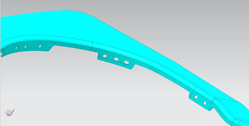
To create splash mount create a sketch on the plane which is parallel to the mounting area and by using project curve option project the curves on to the object. Now use trim sheet option and remove the material.
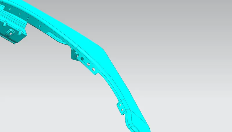
3.DRIP MOUNT
In order to craate drip mount area we have provided with a master sketch. follow the master sketch and create all the extensions using law extension option.
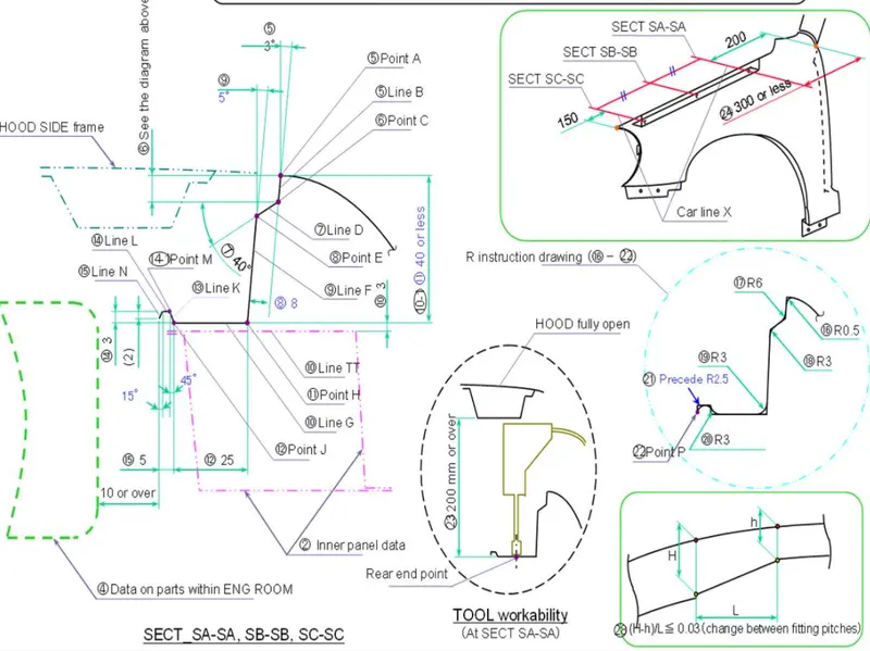
After creating the extensions use face blend option to creare blends except on the area where the dart's are mounted. after sewing create darts as shown in figures and use edge blend option to blend the dart edges. and create sketches by creating a datum plane and emboss the sketches and create circles on the embosses and by using trim sheet option remove the material.
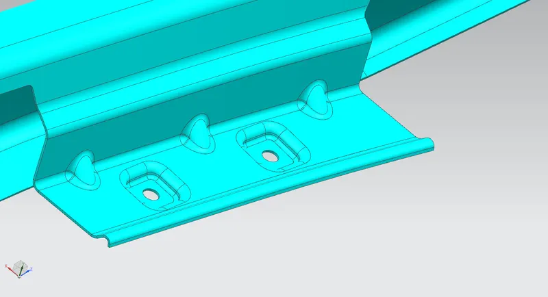
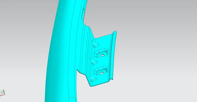
4.SILL MOUNT
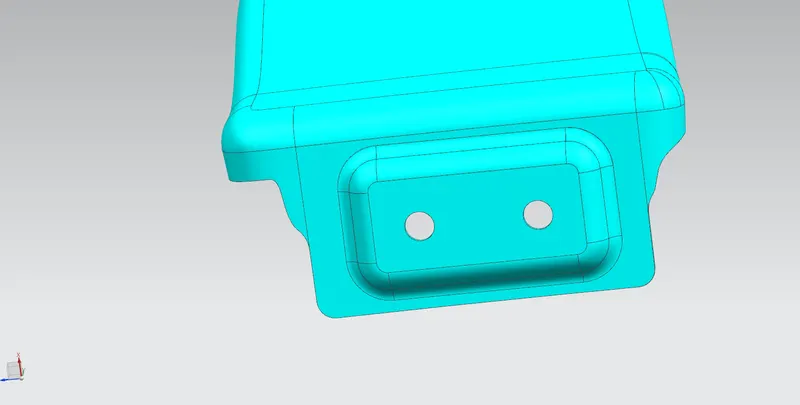
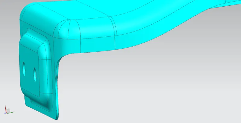
First extend the sheet to required level and b creating bridge curves and using trim sheet command we can easily remove the sharp corners at the edges of the law extension and now create a datum plane and create a sketch for emboss and emboss the sketch and now create a circle on the embossed faces and remove the material using trim sheet option. in this case after thickening the fender body remove the sharp edges at the top by using edge blend option.
5.A-PILLAR MOUNT.
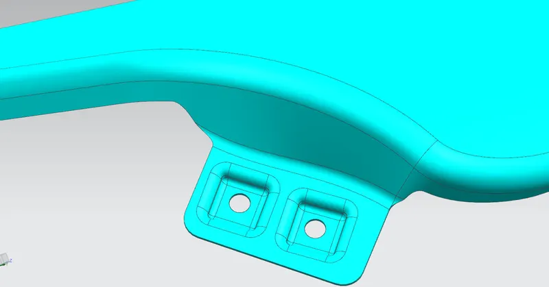
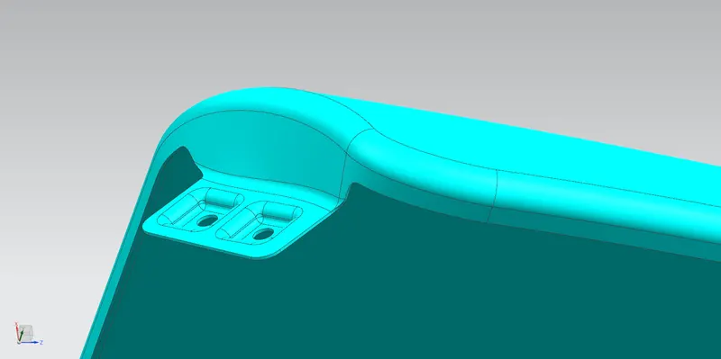
In case of a pillar mounting create a straight lone connecting the edges of trimmed surfaces. now we can use law extensions to extend the sheet. now extend the fender body which is in arc shaped curve and trim the rxtra sheets by using trim sheet option by selectiing these two extensions one by one respectively. after that as we mentioned in the previous stages also use bridge curve and trim sheet option in order to remove the sharp edges. now create a datum plane and draw sketches on the plane for emosses. now emboss the sketches and remove the circle shaped holes by using trim sheet operation to accomodate nut and bolt mechanism.
After creating all the mountings give the thickness to the body by using thicken command. give the thickness as 0.75 mm respectively.
VIEWS OF COMPLETE FENDER
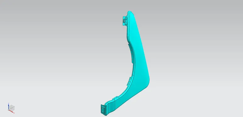
- ISOMETRIC VIEW
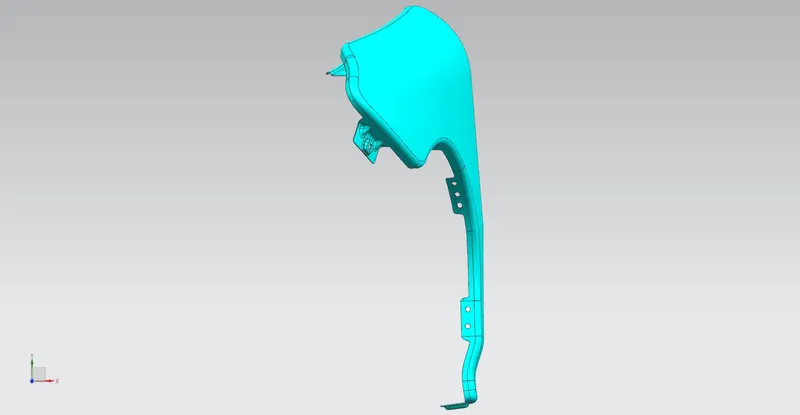
- TOP VIEW
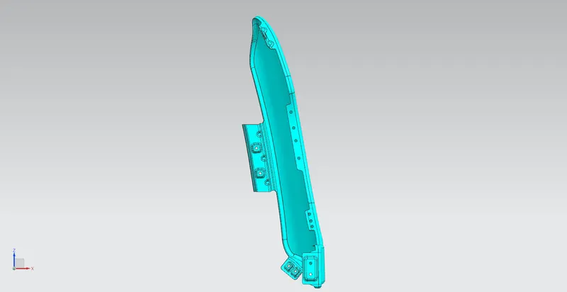
- FRONT VIEW
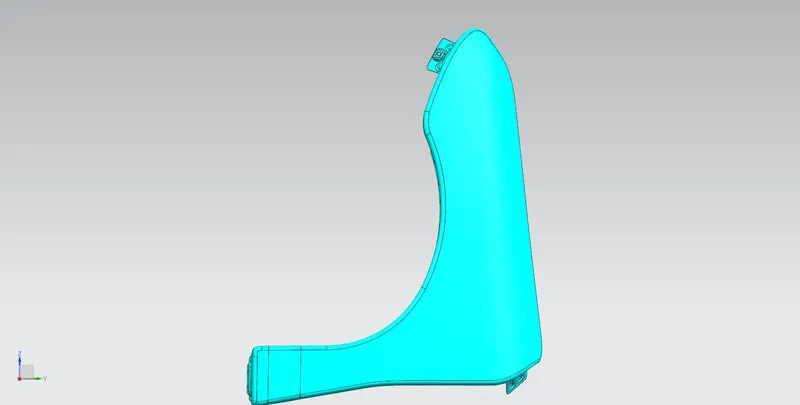
- RIGHT VIEW
CONCLUSSION
The design of mountings of fender of an automobile car such as body mounting, A pillar mounting, sill mounting, splash cover mounting, and drip area mounting has been successfully done using NX application.