Fender Design Challenge
Fender Design:
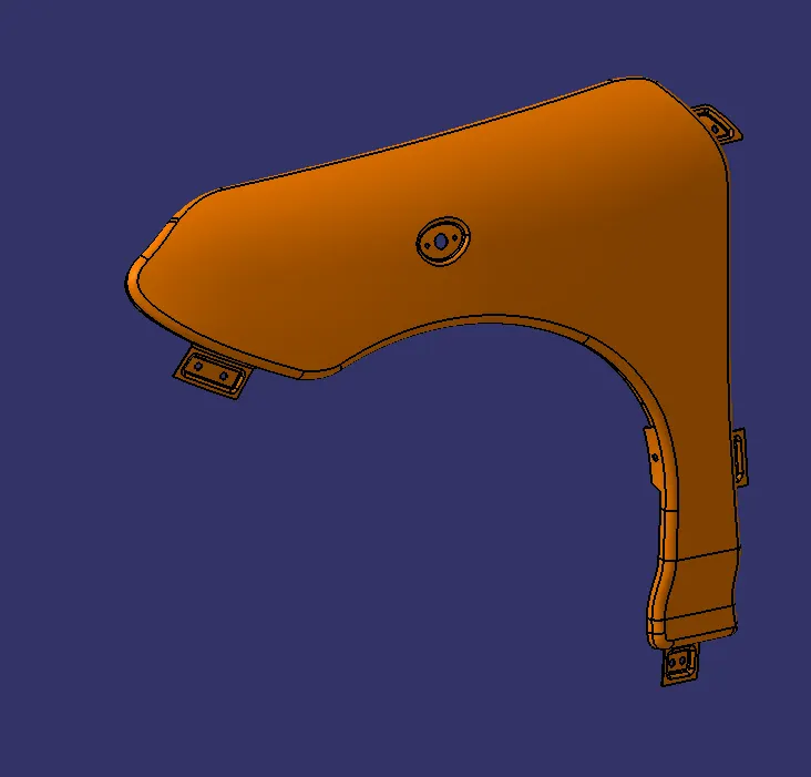
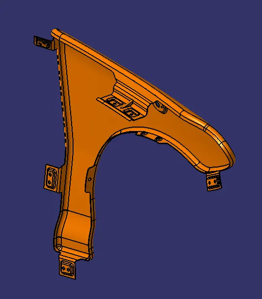
The fender in an automobile is an asthetic feature which is not required to bare any load, it prevents the tyre from flinging tiny rocks and debris into the air. The fender is mounted onto the monoque of an automobile on upto 5 mounting points, fastners are mostly used for mounting the fenders as the mounting points are generally concealed by other features on the car.
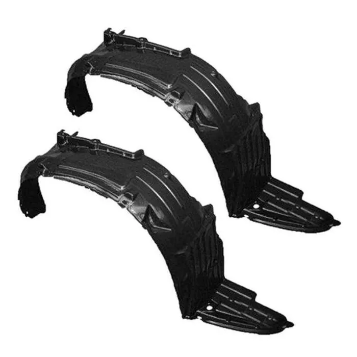
The fender also houses the wheel arch or wheel liner which prevents water and small debri from entering the engine bay or coming in direct contact with the main body of the car, it is generally made of plastic and hence is cheaper and easier to replace.
The main mounting point of the fender is called as the drip area and is the only point where the fender comes into contact with the engine bay. The drip area requires quiet an intensive check on the design part as we need to make sure it does not interfere with any component in the engine bay and there is a minimum clearance of 10 mm between the drip area and any component in the engine bay.
The given cross section for the drip area also accomodates for the spring back effect of sheet metal during sheet metal bending and cutting operation, by keeping the length of the drip area less 40mm from the highest point of the fender. This also ensures that the tool used for fastening the fender to the engine bay can enter and exit without any obstruction.
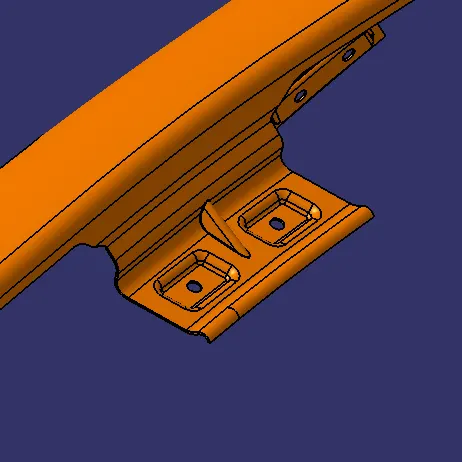
The drip area shown above ensures that the basic requirements are followed, apart from that it is made in accordance with the cross section provided. Since the drip area is an overhanging part a bead is provided to ensure stiffness. In the above design an embosse with 2 regid mounting pionts have been provided which ensure a secure fix.
All other mounting points will be explained in brief hencefourth:
2. Cowl mounting:
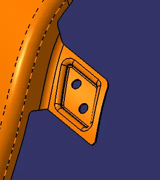
The cowl in the car is the area below the windscreen which houses the wiper motor and wiper mechanism. The fender is connected to this area using fasteners which prevent the fender from viberating which would cause the NVH levels in the car to increse thus making it unplesant for the occupants of the car. The cowl is covered with a plastic cover and hece we can use fastners as they wont be visible to the consumers.
3. A- pillar mounting:
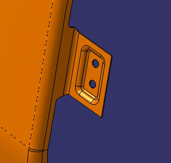
The fender is also mounted to the a pillar to give it a rigid mounting point with the body. While making the A-pillar mounting point we need to consider where the hinges for the front door lie and need to place the mounting point such that it does not interfere with the opening mechanism of the front door.
4. Sill mounting:
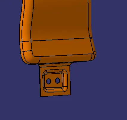
Depending on the design of the vehicle the location for the sill mount will be decided. For the given component it is assumed that the car will have its side skirts coming all the way till the wheel well and hece the mounting point is given below. The side skirts of the car will cover the unasthetic fastners.
5. Bumper mount:
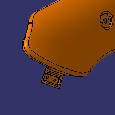
The bumper mounting point on the fender is one of the primary mounting point of the bumper to the car. All the previous mounting points for the fender provide it with enough regidity so that it can carry the bumper without any issues. In the given design 2 mounting points per fender has been provided to ensure a regid and stable fit for the bumper.
Secondary mounting points:
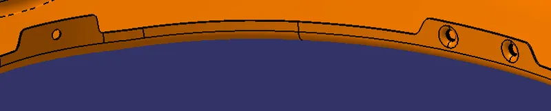

The secondary mounting points on the fender are provided for the wheel arch which is a plastic part without any significant weight, the other secondary mounting point is provided for the indicator. The indicator cutout will be provided for lower versions of the car which do not have its indicators mounted on the ORVM.
All the main mounting points for the fender have been provided with and embosse for rigidity so as to ensure a vibration free fit which is necessary. In the given design a baffle hasn't been provide which is used to reduce the NVH levels in the cabin. If a baffle is provded in the fender additonal mounting points will be required also the addition of a baffle will incerease the overall cost of production of the part