Week 8 - Challenge 1 - Draft Analysis on a Fan Cover
Selecting direction for the tooling axis:
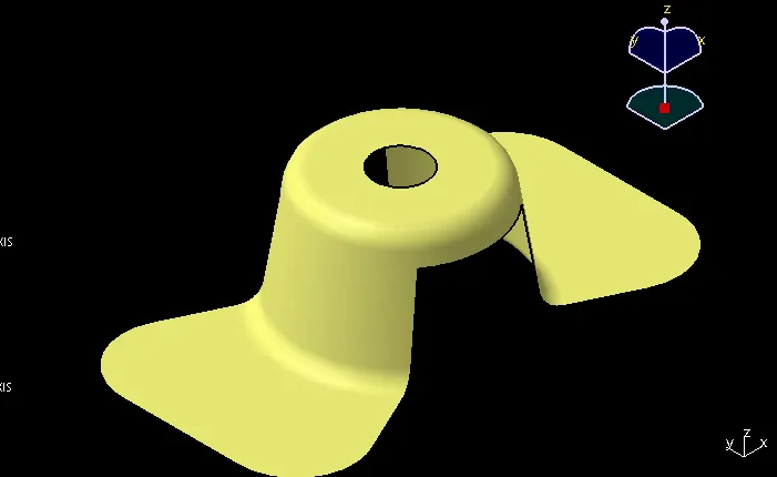
On visual inspection of the surface we can see the obstruction of the hole and the slot for ejection in the X and Y directions. Hence to avoid the involvement of a side core Z direction is chosen for the tooling axis.
Component clearing the X tooling axis:
Bisecting method used- Create a dummy tooling axis approximatly close to where the actual tooling axis should be with the same orientation. Create an axis system on this dummy tooling axis. Now create an intersect between the surface and the zx plane. Select the faces that we feel may cause a problem and extend those lines using the line command. Pick the line command and select bisecting, then select the 2 lines made and select a point on the dummy tooling axis and pick the direction for the new line to be made. Highlight the new line created.
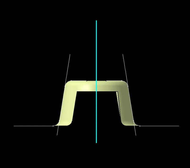
Component clearing Y tooling axis:
Use the bisecting method mentioned above for generating the bisecting line for the faces that may cause a problem in the release of the component.
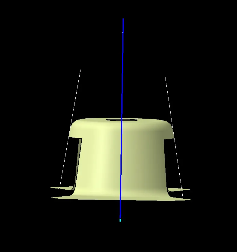
Creating the main tooling axis:
Select the bisecting line command once again and select the 2 lines created for clearing the X and Y tooling axis and the point and create the new bisecting line. This line is the actual tooling axis of the component.
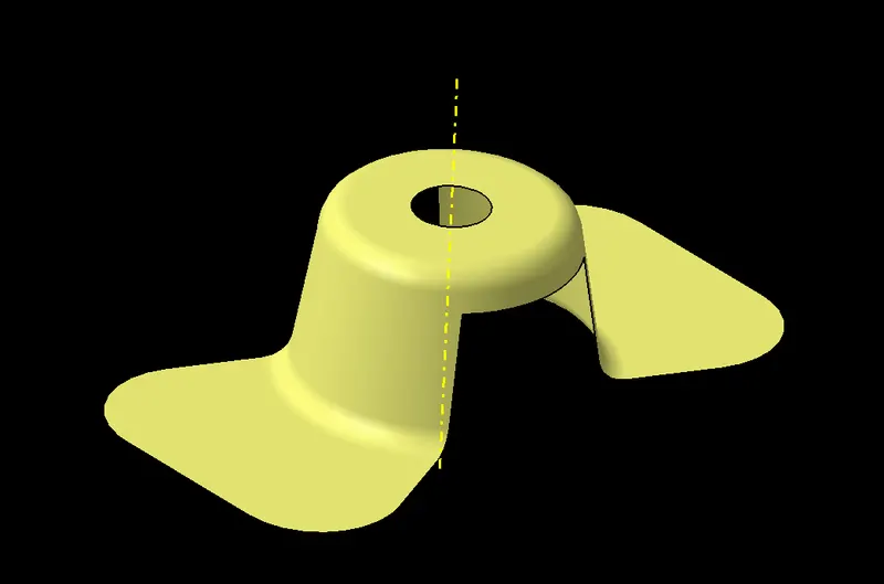
DRAFT ANALYSIS:
- Insert the draft analysis tool.
- Pick the minimum draft value needed for the component.
- Drag the Main axis system and match it with the toolin axis.
- Click on the surface and the component will get coloured according to the parameters selected in the tool.
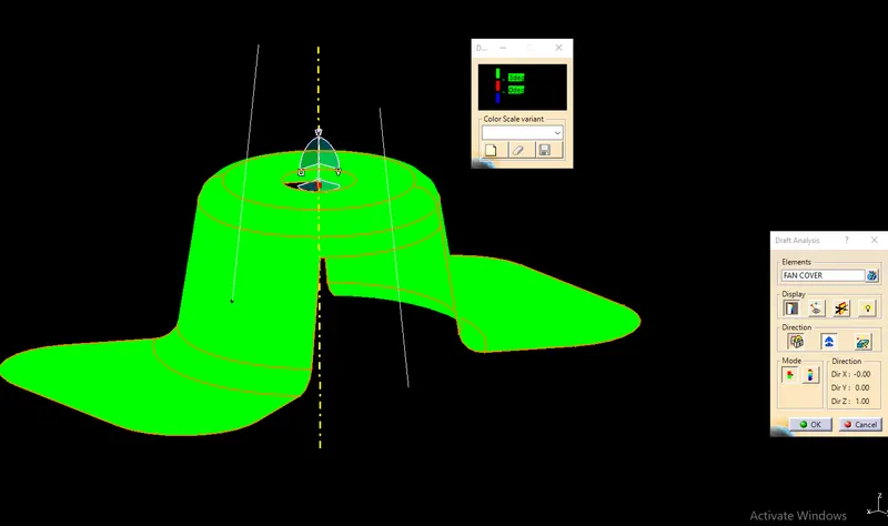
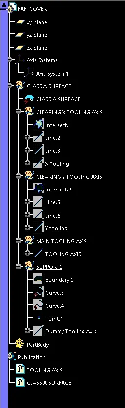
Tree structure and analysis under running point screencapture:
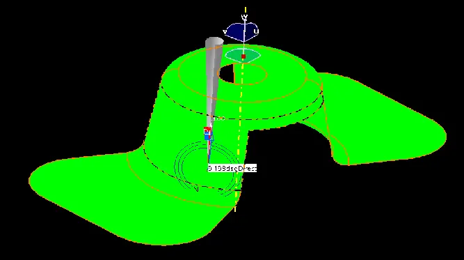
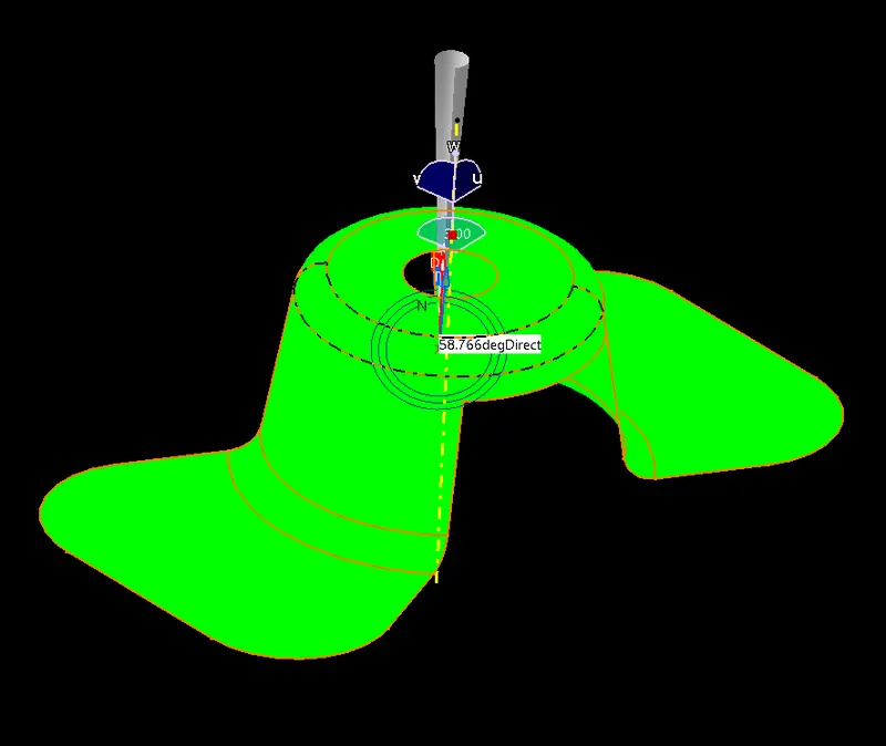
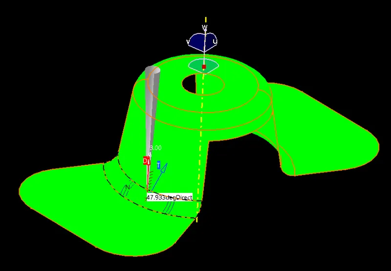
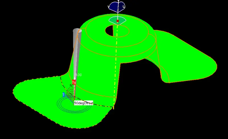
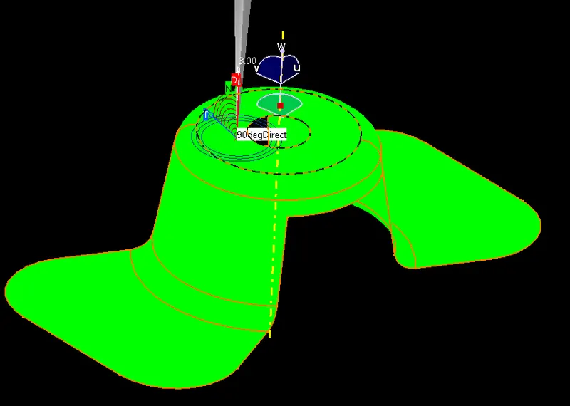
Please find attached the CATpart attached below