Week 8 - Challenge 2 - Base Bracket Design
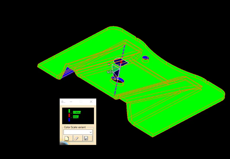
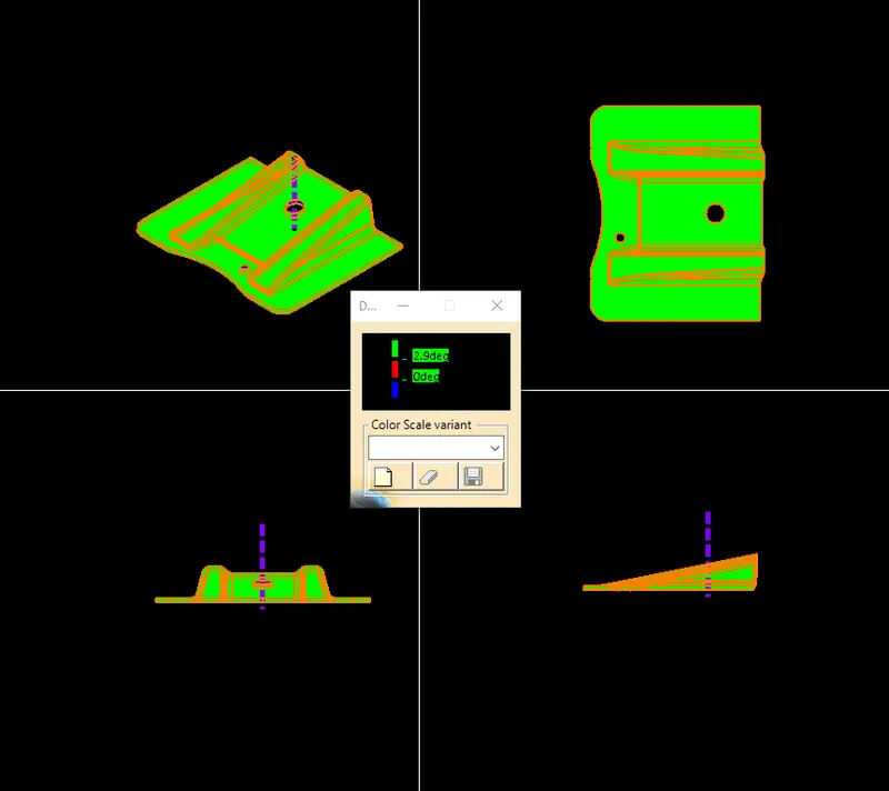
*NOTE:Draft analysis of the solid part shows a negative draft angle for the 2 circles in the component however the circles have been given the proper draft value keeping in mind the ejection of the component from the mould.
Creation of the tooling axis:
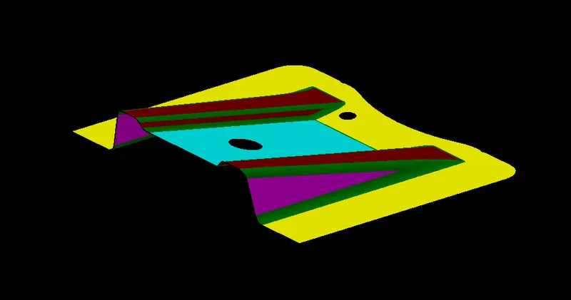
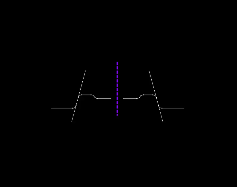
On close inspection of the class A surfce it is found that 2 faces (Highlighted in pink) are most probable to prevent the component from releasing after cooling. Hence these faces were selected in making the tooling axis. Bisecting method: Create an intersection with the class A surface with the YZ plane and select the profile of the faces that will cause a problem and extend the lines. Now create another line and pick the bisecting option and select the lines and a point for projection and the direction and plot it, this is the tooling axis.
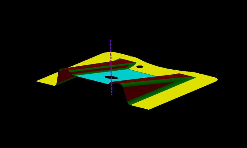
Making surface B:
- Select the faces in maroonn and extract them. Follow it by untrim and extrapolating with point continuty for those faces and then trim them with the shape needed as per the Class A surface.
- Select the face in cyan and extract, untrim and extrapolate it.
- Select the yellow face and do the same.
- Trim all of these surfaces according to the Class A.
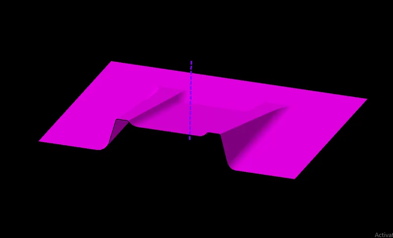
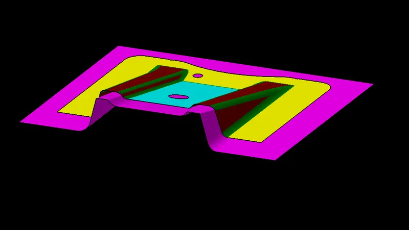
Creation of Surface C:
- Use Multiple extract on the back and front borders of the Class A surface.
- Use the Sweep command and pick the profiles extracted and the Tooling axis as direction.
- Now extrapolate the end points of both the surfaces and trim them to form a single body.
- Use steps 1 and 2 for the circles as well.
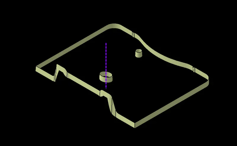
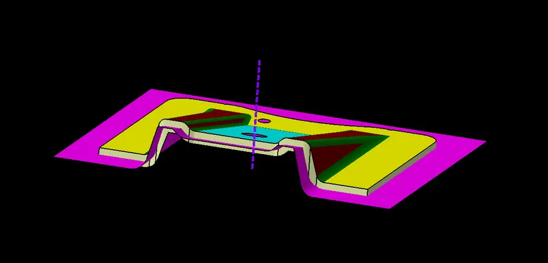
Class A, Surface B&C intersecting.
Final Trims: Use the trim command and trim all of the surfaces as per the requirement to get a complete closed body surface.
Use the closed body command and make a solid out of it.
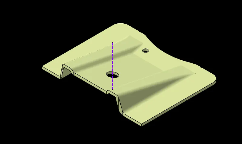
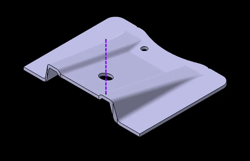
Draft analysis:
Class A:
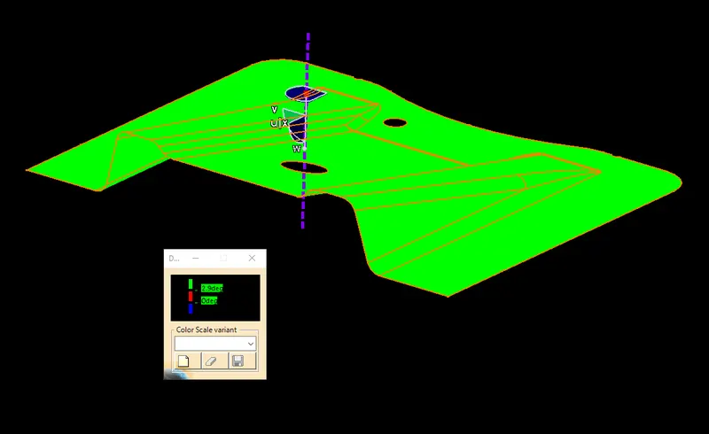
Closed surface:
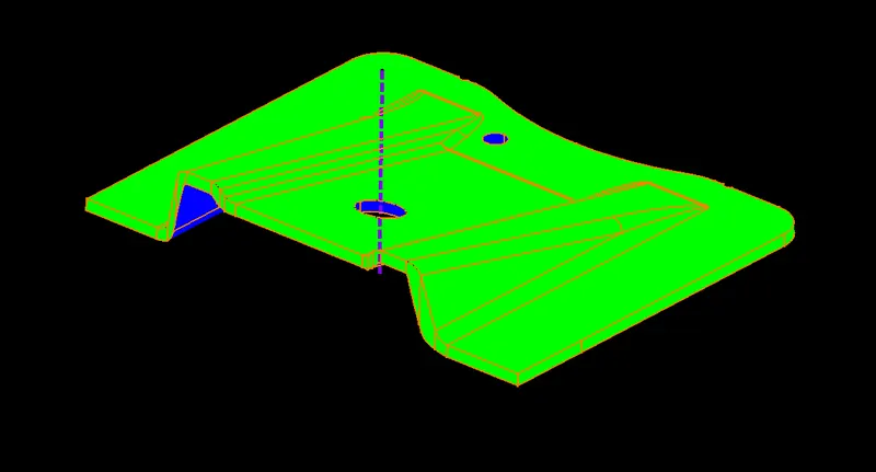
Solid body: