Week 8 - Challenge 3 - Switch Bezel Design
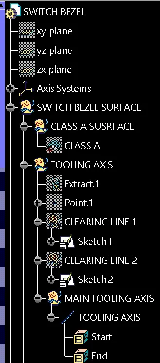
Creation of Main Tooling Axis:
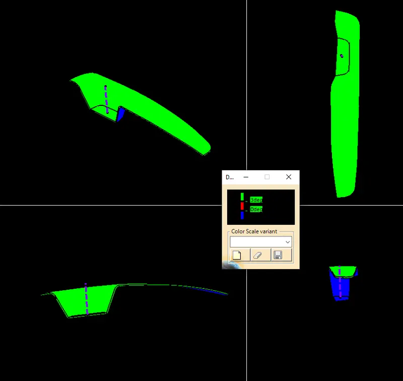
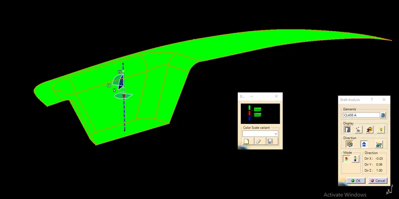
On visual inspection of the class A surface the faces highlighted in blue are indentified as faces that may cause problem in the ejection of the component from the mold. Hence the Z- axis is chosen as the direction for the toolling axis.
- Extract the bottom face. Make a point on this surface with offset zero so as to center it and consider this point as the origin.
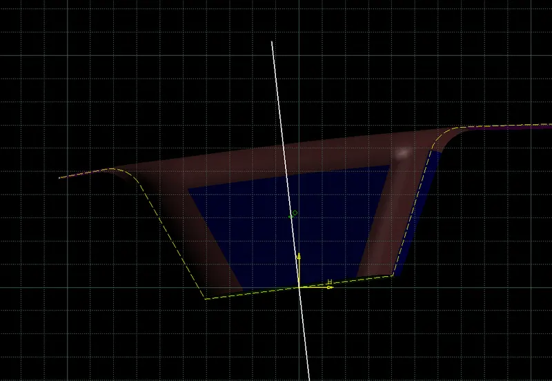
- Hence a sketch is made in the YZ plane and the intersection of the class A surface is taken, now a bisecting line of these 2 faces is taken and plotted.
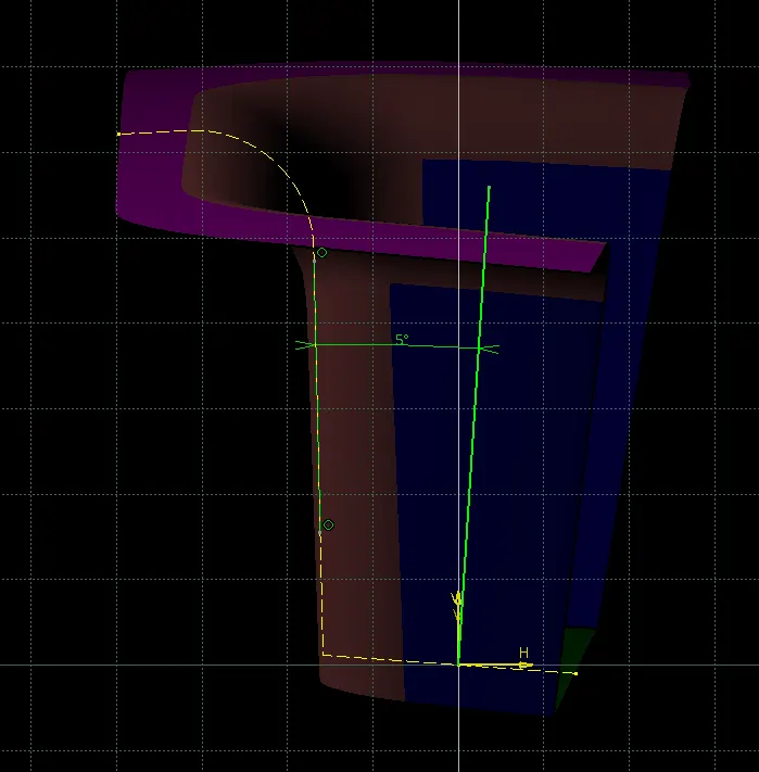
- Another sketch is made on the ZX plane and and the intersection of the class A is taken again, since there aren't 2 faces to take a bisection line just draw a line with the origin and give an angle constrain of aroud 5 degrees for a clear draft analysis.
- Take both thes lines and make a bisection line with the origin to get the tooling axis.
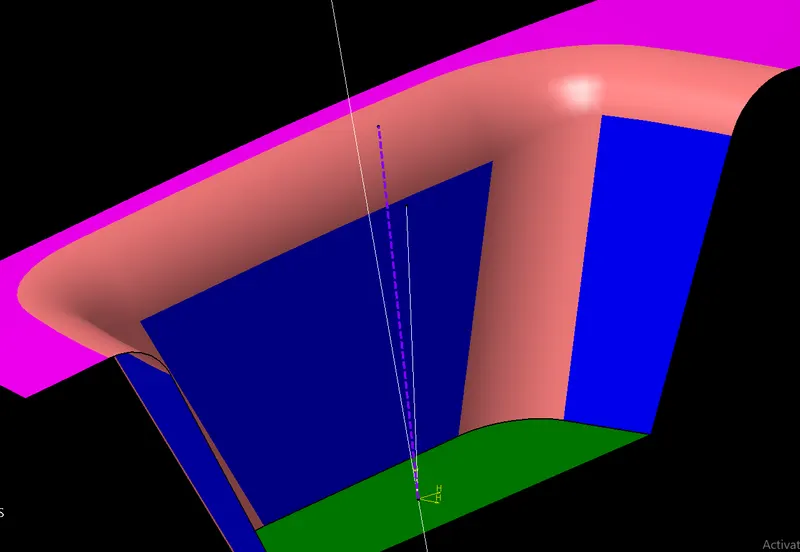
Draft analysis of class A surface:
Take a draft analysis of the class A surface to ensure that the tooling axis selected is appropriate.
Creation of B surface:
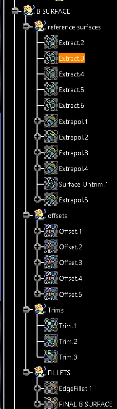
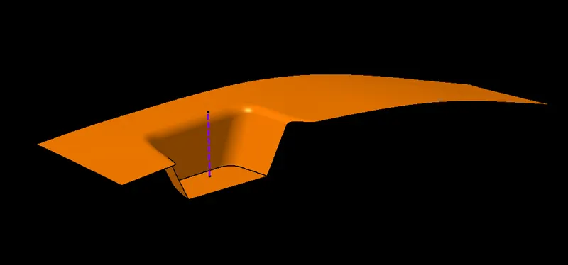
- Select all the faces of the component and extract and untrim them.
- Extrapolate all of these surfaces to ensure that they inersect.
- Take an offset of these faces below the class A surface according to the thickness of the component needed.
- Hide the initial faces and trim the offset faces.
- Give the necessary fillets keeping in mind the rules for filleting.
Creation of C surface:
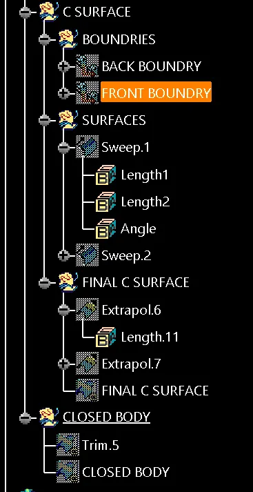
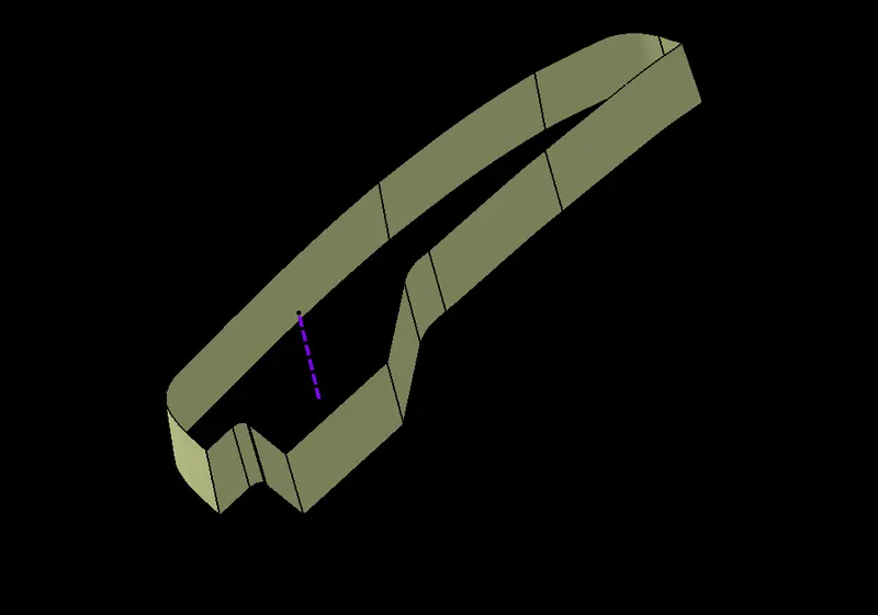
- Multi-Extract the boundry of the class A surface in 2 parts i.e. front and back
- Select the sweep command with draft direction and generate the 2 surfaces.
- Extrapolate and tirm the surfaces to form a single surface.
Creation of closed body:
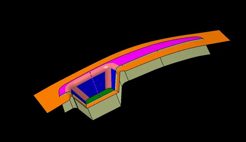
- Select the A,B,C surfaces and trim them appropriately.
- Check for any open boundries with the boundry or join command.
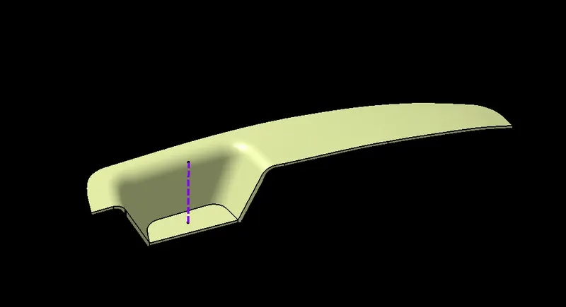
Creation of solid body:
Use the closed body command in the part workbench to create a solid body.
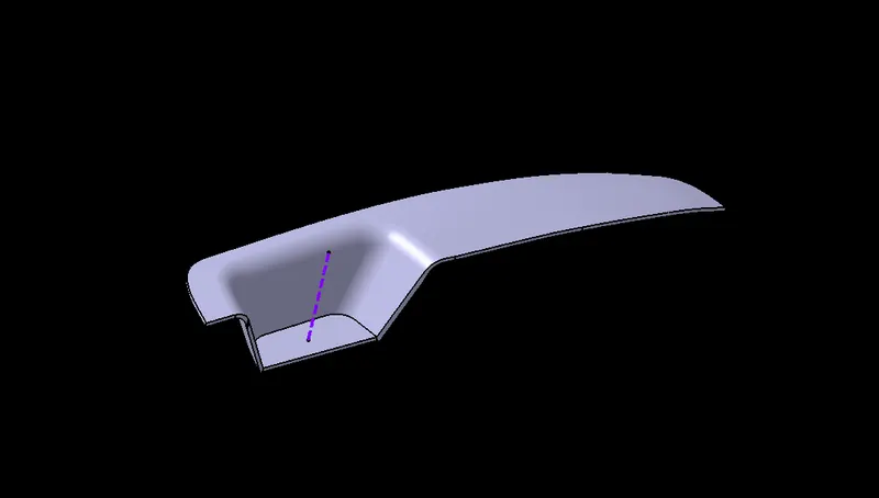
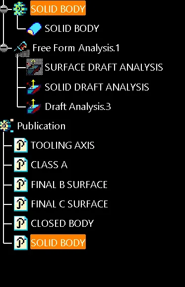
Draft analysis and Tree structures: