Fender Design Challenge
DESIGN OF FENDER USING NX-CAD
What is a fender?
Fender is the US English term for the part of a vehicle body that frames a wheel inside it. Its primary function is to prevent sand, mud, liquid, and other materials from being thrown into the air by rotating tires. Fenders are typically rigid and can be damaged by contact with the road surface. Sticky materials, such as mud, may adhere to the smooth outer tire surface, while smooth loose objects, such as stones, can become temporarily embedded in the tread grooves as the tire rolls over the ground. These materials can be ejected from the surface of the tire at high velocity as the tire imparts kinetic energy to the attached objects. For a vehicle moving forward, the top of the tire is rotating upward and forward and can throw objects into the air at other vehicles or pedestrians in front of the vehicle.
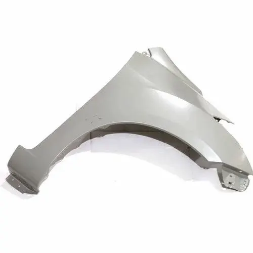
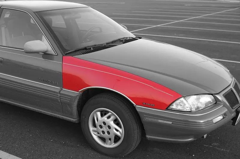
Types of Fender
Fender is basically of 2 types.
- Full Bumper type
- Half Bumper type
Presently we are using half bumper type. The reason is when we were using a full bumper type fender, the blank which we were using is very big, and we have quite lots of wastage from the blank. But in the case of the half bumper type, the case is the opposite. Here is the amount of scrap production is very low.
Mounting points of the fender.
The 5 major mounting point of a fender is
- Body
- A-Pillar
- Sill
- Cowl
- Drip
Real image of fender Drip area of TATA TIGOR.
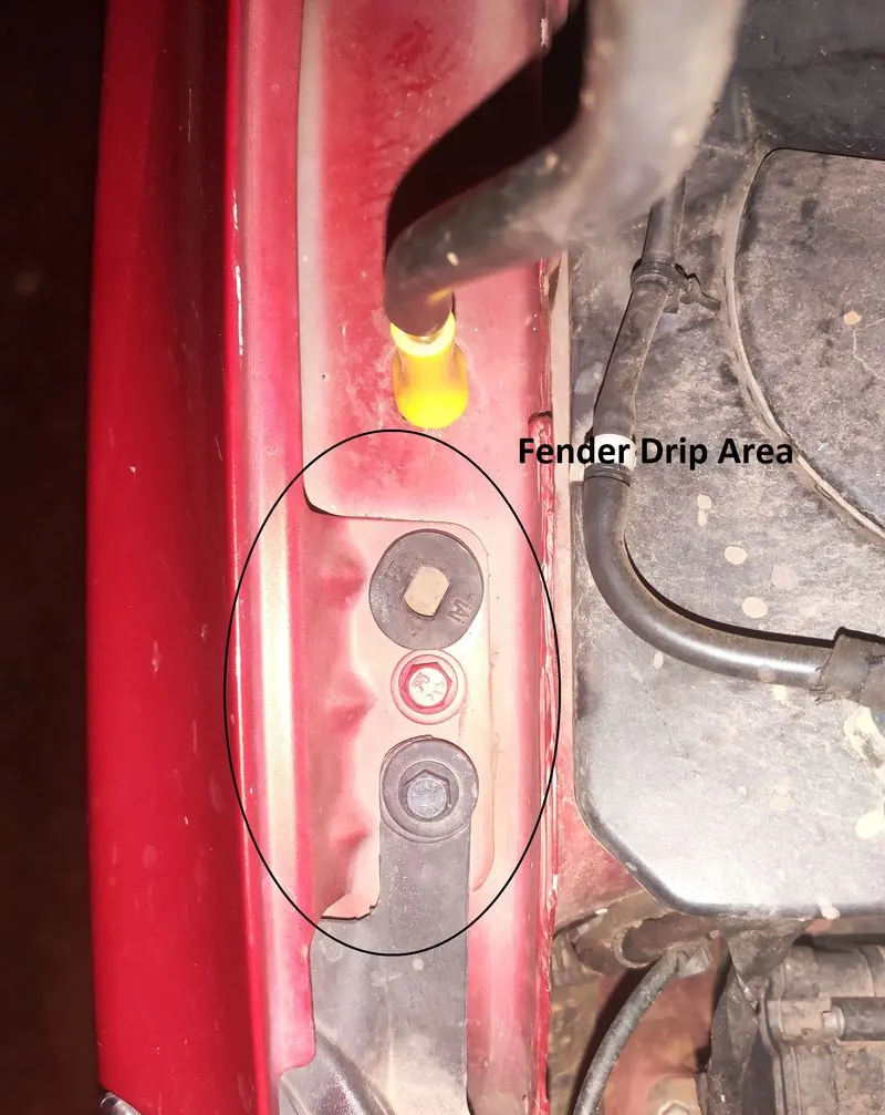
Here we will design the fender drip area, which is the most difficult part of the fender.
The drip area is the joining between the fender and the engine mounting area.
The design we will consider here is the below-shown image.
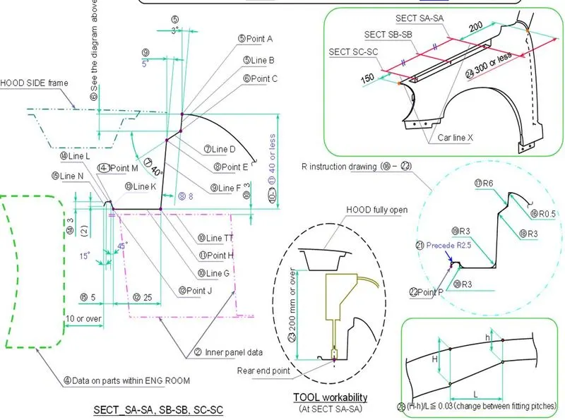
Here as shown in the image we will draw our fender drip area using NX-CAD.
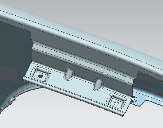
As shown in the above image we have drawn the fender drip area according to the given dimension.
As shown in the above image we have drawn the fender drip area according to the given dimension.
Here we have used different options to create the fender drip area.
The options are
- Offset In face
- Curve on Surface
- Trim Sheet
- Law Extension
- Offset In Face
- Datum Plane
- Intersection Curve
- Sew Dart
- Face Blend
- Edge Blend
- Bridge Curve
- Extend Sheet
- Emboss
Design Methodology to draw Fender drip area.
First, we will open the skin part of the fender.
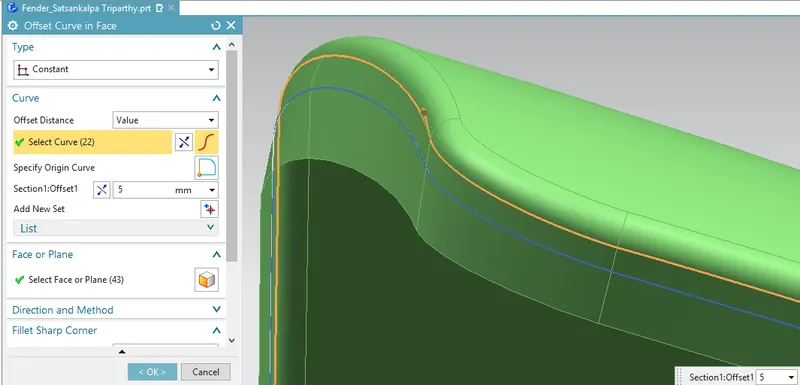
After that, we will offset the curve(shown in orange color) with a value of 5mm.
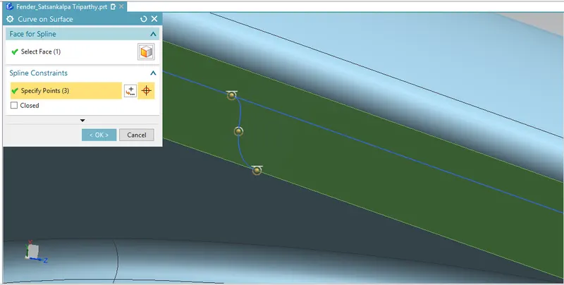
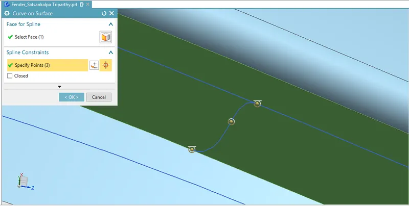
Then we have created a curve on the surface on two sides.
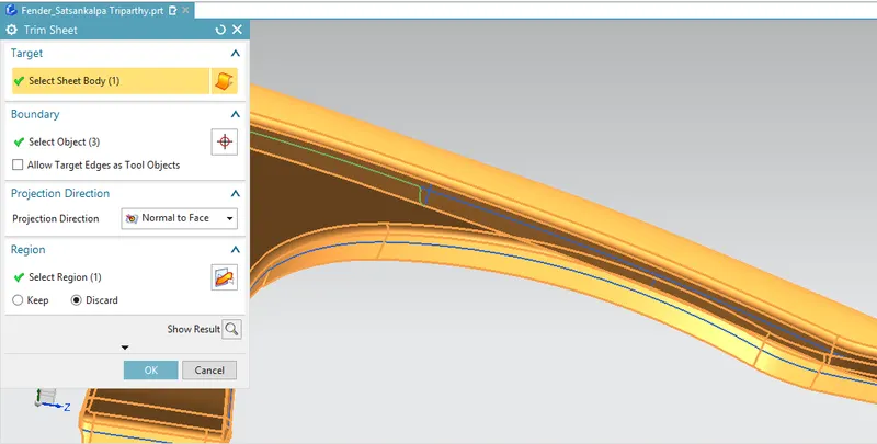
Then after we have trimmed the sheet.
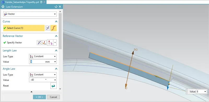
We have created a law extension and the dimension are shown in the picture.
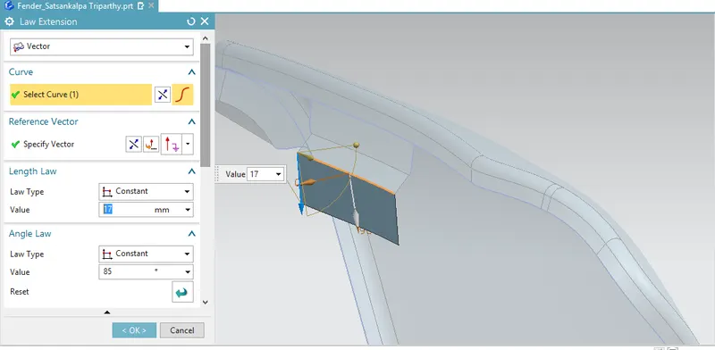
Then after we have created 2 dirts as per drawings.
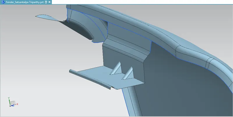
After that, we have created the emboss and the trim sheet for the creation of the bolt mounting area.
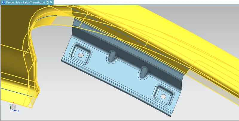
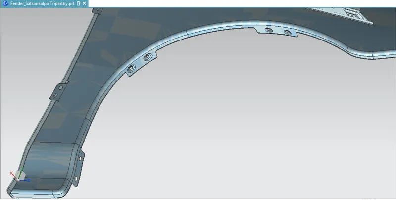
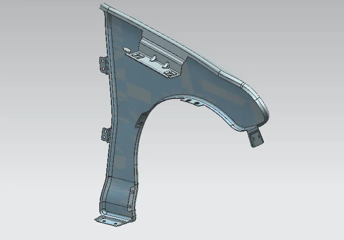
Different mounting areas of the fender.
Drip
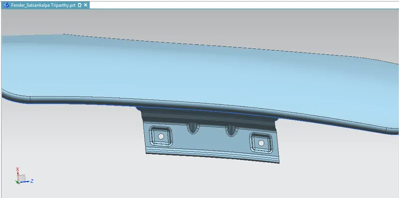
Sill
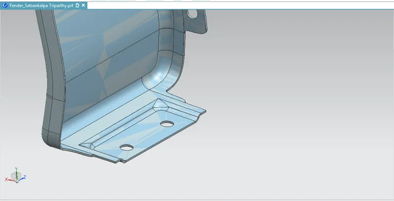
Body
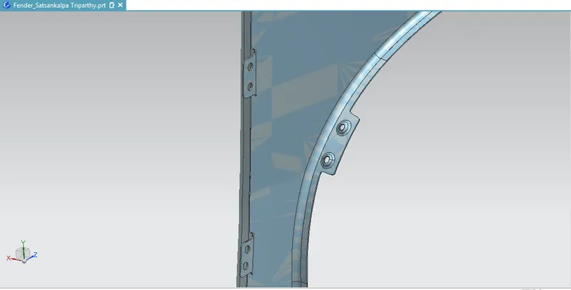
Baffle Mounting Area/Fender Liner Mounting Area.
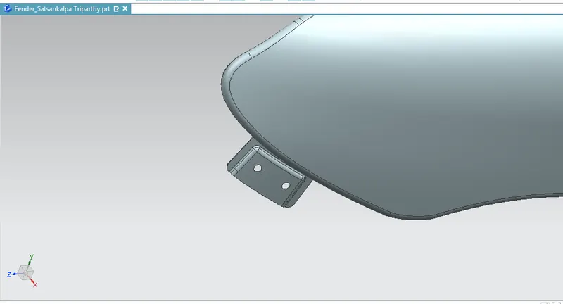
Bumper Mounting Area
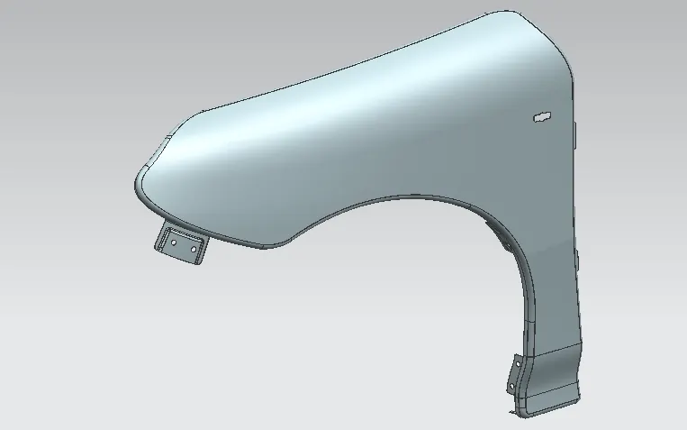
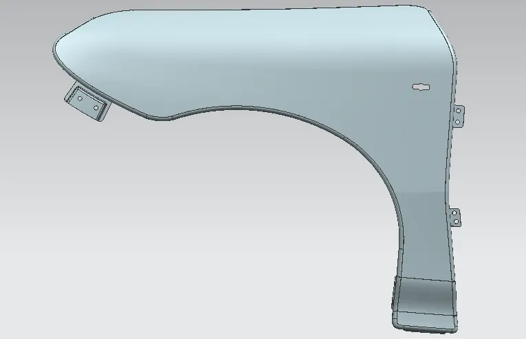
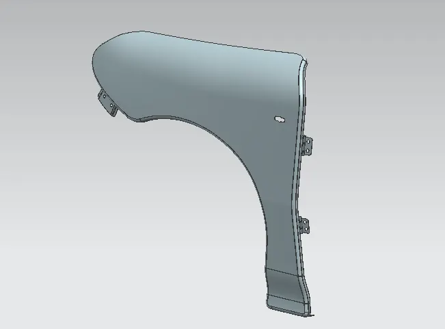
FINAL IMAGE OF THE FENDER WITH MOUNTING AREA
Conclusion
- Here we have created the fender using the different tools in NX.
- The design has approached according to the given data and skin image.
- I would thank and I am very much grateful to Mr. KASHYAP KUSHAGRA sir, to assist me in every step to finalize the challenge.