Fender Design Challenge
TITLE- Design front fender of car using nx cad.
OBJECTIVE-Design a front fender from the given class A surfacing with Drip area, Bumper mount, Sill area, Baffle mount and a A - Pillar mount.
SOFTWARE USED FOR DESIGNING THE FRONT FENDER
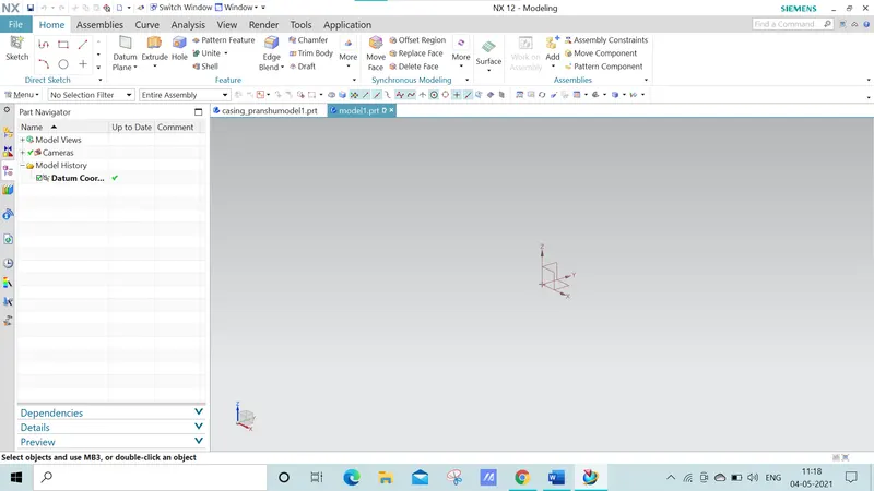
NX, formerly known as "unigraphics", is an advanced high-end CAD/CAM/CAE, which has been owned since 2007 by Siemens PLM Software. In 2000, Unigraphics purchased SDRC I-DEAS and began an effort to integrate aspects of both software packages into a single product which became Unigraphics NX or NX.
INTRODUCTION
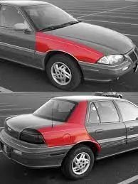
- Fender is the US English term for the part of automobile ( vehicle body ) that frames a wheel well ( the fender underside).
- Its primary purpose is to prevent sand, rocks, and other road spray from being thrown into the air by the rotating tyre.
- When vehicle is moving , tires picks up stones and other and hurl them in all directions . fenders are basically present to prevent any injuries to pedestrian and contains the motions of these particles.
TYPES OF FENDER
Fender are categorized into 2 types-
- Full bumper type fender
- Half bumper type fender
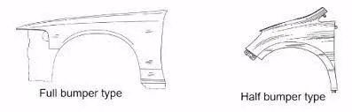
Half bumper type fender nowdays are widely used because in half bumper type we can produce two half type bumper from a single plank whereas in full bumper we can produce only one bumper from a single blank. These saves a lot of material as well as weight is also reduced.
Difference between fender and bumper?
- A bumperis located on the front and rear of a vehicle. The purpose of a bumper is to absorb the impact of minor collisions.
- In the early days of the automobile, bumpers were a more distinct component that was noticeably separate from the rest of the car’s body. But as automotive technology advanced, bumpers became more integrated with the rest of the car’s body. The purpose of the modern bumper remains the same, but the bumpers on many vehicles (namely sedans and crossovers) are less visually noticeable than they once were.
- a fender is merely a housing for the wheels that prevents road debris from being thrown up by the rotating tires. However, fenders are also able to absorb impact from minor collisions. In this way, the fender can act as an extension of the bumper in terms of its ability to absorb the energy from a collision.
MANUFACTURING PROCESS OF AUTOMOBILE FRONT FENDER
- a manufacturing process for automobile fender, comprises the following steps:
- The first step: open straight snips plate: first select applicable cold coiling specification, cold coiling is opened flat; Then according to production material specification, will open cold coiling after flat and be cut into into the iron plate of corresponding size; Finally the iron plate after shear is cleaned to iron filings;
- Second step: oil pressure, punch press: first iron plate is extended; Secondly to its trimming and punching; Then to its flanging and shaping; Finally after shaping completes, then carry out one-off hole-piercing; Completed the making of lappet plate body;
- The 3rd step: the 1# smallclothes of processing lappet: first iron plate is stamped out to required outline blank (blanking); Then to completing the further moulding of iron plate of outline blank; Finally it is carried out to punching;
- The 4th step: panel beating assembly welding: first 1# smallclothes are carried out to spot welding M6 nut; Then 1# part point is welded on lappet; Finally lappet body and 1# smallclothes are carried out to sanding thorn and ending.
- the manufacturing process of automobile fender according to claim 1, is characterized in that: the trimming of described second step, punching can replace by Radium art.
- the manufacturing process of automobile fender according to claim 1, is characterized in that: the flanging of described second step, shaping can be replaced by punch press punching, steel seal technology generations.
HOW TO REPLACE FRONT FENDER OF A CAR?
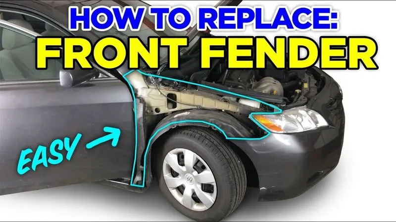
The fenders on modern cars have become more integrated with the rest of the body, but don’t worry — they can be replaced just like most other automotive components.
Here we’ll briefly walk you through the process of replacing a fender. Keep in mind that the process might vary slightly from vehicle to vehicle.
- Remove the retainers that attach the fender to the bumper (these might be screws, clips, or something similar).
- Lower the bumper slightly to get it out of the way.
- Remove anything that might be mounted near the fender such as the lights.
- If replacing a front fender, remove the bolts under the hood that hold the fender in place.
- Remove the fender.
- Do the reverse process to install the new fender.
FRONT FENDER MOUNTINGS
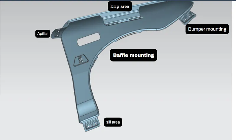
The following are different mounting areas on fenders and are fastened by fasteners as per design and requirements
- DRIP AREA
- A PILLAR
- SILL AREA
- BUMPER MOUNTING
- SPLASH COVER/ WHEEL WELL MOUNT REGION
DRIP AREA
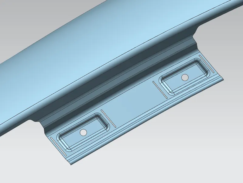
- It is the area through which fender is attached to the engine housing unit through fasstners.
- To develop a fender drip area we needs a master sketch.
- According to the master section provided there should be some considerations to be followed while design the drip area of fender.
- Fender surface and the point will be provided by the styling team.
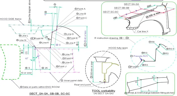
- After that we need to go as deep as 9 mm inside and open an angle of 3 degree.
- The 3 degree opening is given for drawing regions if it will be less than 3 degree then it will become very difficult for production purpose so minimum 3 degree is provided.
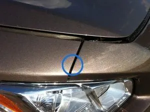
- The gap prevent visibility inside the engine compartment.
- Hood side drip depth must be 40 mm or less because maximum productivity is achieved at the depth of 40mm.
- If the depth exceeds 40 mm , rigidity bead is to be provided also, forming is not feasible if depth exceeds 60 mm due to wrinking and springback effect.
- The horizontal land area where hole and embosses are done should be near about 37mm.
- And at end of flat surface and structure is given to strengthen the part.
- There should be about 10 mm gap from the endmost part of fender to the engine room compartment .
- This gap are given to prevent hitting while assembly the commodities in engine room.
- From the back side of front fender, there should be 200mm clearance for cowl mounting area . in cowl area wiper motor is to be attached.
- From front side of front fender , there should be 150 mm clearance for head lamp housing unit.
- Remaining area are used for deign drip area.
- Height of fender can be minimum 80 mmfor child and adult.
- Drip area will not reach the engine assembly due to restriction of 40mm length , so there will some l shaped bracket to connect it.
A PILLAR MOUNTING
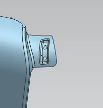
- A car has many pillars according to the design and the style of it .
- It is the number of vertical positions in a car.
- In a sedan car there will be three pillar.
- In a hatchback model, there will be four pillar .
- The front most pillar is known as a A PILLAR.
- In the fig A PILLAR frame of chassis is mounted so that it is rigidly attached to the body of car.
SILL AREA
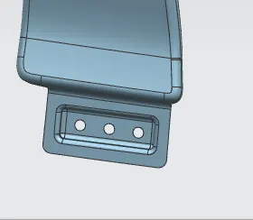
- The rocker panel or sill is the part of car traditionally running between the wheel arches beneath the doors.
- In the fig sill area is shown
BUMPER MOUNTING
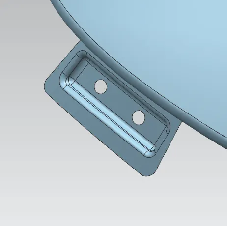
- A bumper is a structure attached to or integrated with the front and rear ends of motorvehichle , to absorb impact in a minor collision, ideally minimizing repair cost.
- In the figure bumper mounting area is shown.
BAFFLE/SPLASH MOUNTINGS
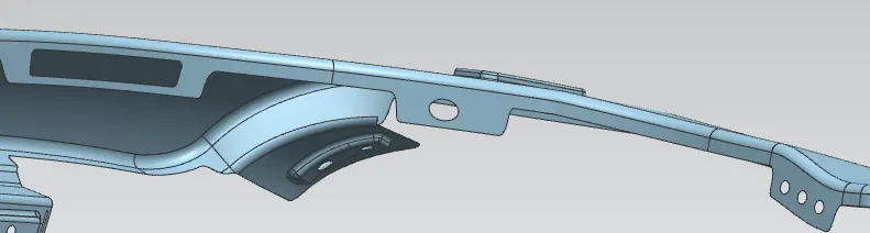
- In order to stop all the debris entering into the engine room and other components splash protector mountings is been introduced. It is just required area to hold the splash protector , so holes or slots are provided as per requirement.
WHEEL ARCH AREA
- WHEEL ARCH is a semi circular edge of the fender which houses wheel-well. The wheel arch gives access to the wheel and other components attached to it. It also allows the tilting of wheels while steering to both sides without causing any interference between wheel and body.
- The wheel arch is designed in such a way that it allows any possible kind of motion that the wheel can have and to prevent any material that could fly aut from the wheel during motion and done for protection for pedestrian.
- The wheel arch area of fender is usually designed for the purpose of protecting the BIW from stones and also provide safety for the pedestrian.
- To check the clearance between fender and the wheel , there are certain standards all over the world.
- European standard
- American standard
- Japanese standard
European regulation requirement
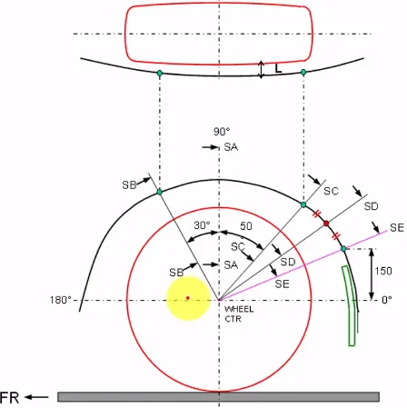
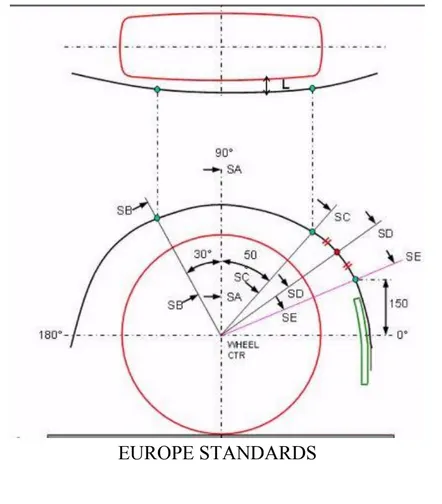
- Measure CL L at sections SA-SA SB-SB SC-SC SD-SD SE-SE and produce CL check chart to validate.
- At all five sections the CL L value should be greater than 10 mm to satisfy the European regulations.
- Wheel guard requirement – the value of “a” shall be more than 5 mm at a line of 30 degree forward and 50 degree rearward from the central vertical axis of axis of wheel.
Japanese regulations standard
- Measure clearance L of tyre , hub , cap and fender In the different positions within area K and produce clearance check chart to validate.
- Clearance must be greater than 5 mm in all three positions.
- Wheel guard requirement – the value of ‘a’ shall be more than 5 mm at a 30 degree forward and 50 degree rear ward from the central vertical axis of the axis of wheel.
US regulation standard
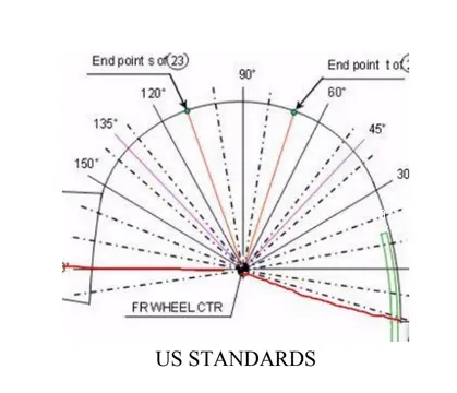
- Make clearnce check details on all positions from – 100 degree to 100 degree and make clearance check table.
- All values should be greater than 5 mm to satisfy the regulations .
- The value of ‘a’ shall be more than 5 mm at a line 30 degree forward and 50 degree rearward from the central vertical axis of wheel.
Need of regulations
In order to ensure the safety , the designs of the passenger car fenders are constrained by implementing regulations that control the wheel arch area.
There are many regulation allarround the world with different road conditions in different countries.
COMMANDS USED IN DESIGNING OF FRONT FENDER(DRIP AREA, SILL MOUNTING , A PILLAR,BUMPER MOUNTING , BAFFLE AREA)
- Offset Curve on surface
- Projected curve
- Extend
- Trim sheet
- Emboss
- Law extension
- Face blend
- Edge blend
- thicken
OFFSET CURVE ON SURFACE
Offsets curve along the selected face. Offset adopts surface even if the surface blended or face has sharp corners.
PROJECTED CURVE
command to project curves, edges, and points onto faces, faceted bodies, and datum planes. You can direct your projection toward, or at an angle to, a specified vector, a point, or along the face normals. The software trims projected curves at holes or edges of the faces.
EXTEND
Use the Extension command to create an extension surface sheet at a surface edge or corner.Edge-based extension surfaces have two methods of definition, Tangential and Circular.
Trim sheet
this command help to trim sheet through a slelected curve , surface , plane .
EMBOSS
Emboss Body now addresses cases where a solid tool body intersects the boundary of a sheet target body.
LAW EXTENSION
The “Law Extension” command extends the curve or edge on the surface to create a sheet body. You can create different types of extensions by changing the rules in the Length Law and Angle Law in the command dialog box.
FACE AND EDGE BLEND
Edge blend command creates smooth tangent faces between faces which connected on edge.
THICKEN
Thicken command to offset one or more connected faces or sheets into a solid body. Thickening occurs by offsetting the selected faces along their face normals, and then creating sidewalls. Note. The Thicken command is similar to the Offset Face command.
PROCEDURE
- offset curve on surface on a given body. Specify the face and points.
- Go to surface and click on trim sheet and then law extension .
- Go to curve on surface on both sides and then trim the sheet.
- Offset another curve on surface and select datum plane on curve . enter the dimension of 150 mm and do intersection curve by selecting the face and plane.
- Go to curve on surface on both sides and trim the discard region that we don’t want.
- Now for bumper surface do the same as done in drip area.
- Moving on drip area first law extension select the vector and design according to master sketch.
- Start adding fillets i.e. face blend.
- Now create mounting on drip area (mounting with flat surface) for flat surface we need to create emboss. For that create asketch project it and then emboss . create holes also .
- Provide relief corners.
- Create same curve as done earlier for bumper mountings and sill area and also create mountings on them by creating skrtch , project curve, emboss, trim sheet.
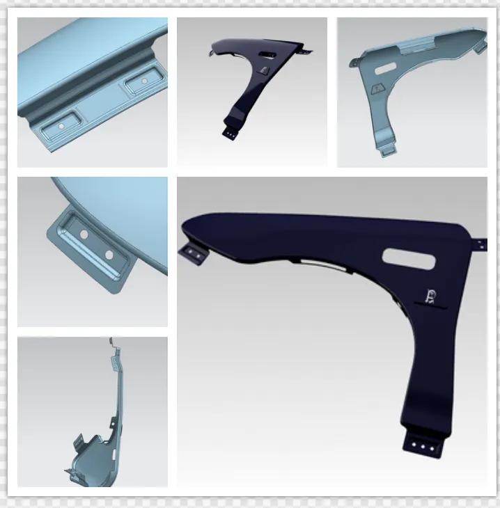
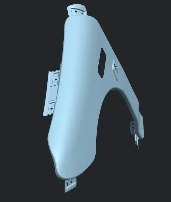
SCREENSHOT OF THE MODEL
Development of Fender Structure for Pedestrian Protection 2009-01-1206
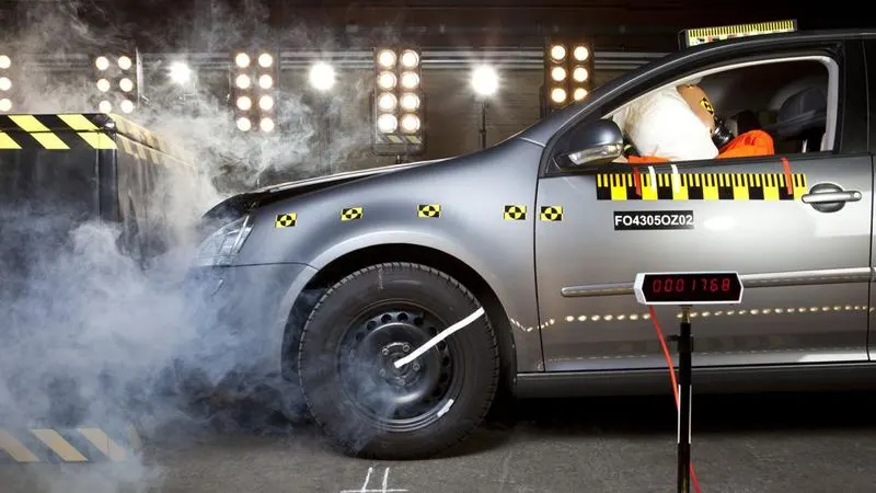
In a typical passenger car-to-pedestrian collision, it is noted that the pedestrian’s body rotates after the initial contact with the hood leading edge. Consequently, the head often crashes into a stiff part of the car body, resulting in serious or life-threatening head injuries. Therefore, to reduce pedestrian fatalities, it is important to improve vehicle structures so as to mitigate head injuries.
Front fenders are one example of such stiff body parts with small impact energy absorption capability. This paper reports on the development of a new front fender structure designed to mitigate pedestrian head injuries in passenger car-to-pedestrian collisions. The new structure is characterized by fender supporting brackets that incorporate a break-off mechanism in the riveted joints between the fender and brackets. It maintains necessary joint stiffness for normal driving use while having sufficient impact energy absorption capability because the riveted joints rupture when they are subjected to a certain level of impact force during a collision, thereby promoting deformation of the fender cross section.
CONCLUSION
Thus the drip area , bumper mount, baffle mount , sill mount and a pillar mount are designed for the front fender from the styling surface is provided.