Fender Design Challenge
AUTOMOTIVE FRONT FENDER DESGN
INTRODUCTION
This part is housing of wheel. The main purpose of this fender is to prevent the pedestrian and the car’s class A surface from being exposed to the chipping materials like sand, mud, grits, etc. when the tire rotates. These unwanted spitting of tire can cause nuisance to the pedestrians and co-drivers on road, this case gets even worse in rainy days. To keep the situation in control the fenders were used. This fender protects the engine compartment from these chipping case. It also helpful in hiding the welded areas from the viewers. In this project the fender is designed by adding the required mounting areas from the given styling surface. Design is done with features of manufacturing feasibility. Finally the design is sewed to produce the required thickened part of 0.75mm thickness.
SOFTWARE USED
SIEMENS NX12
FENDER
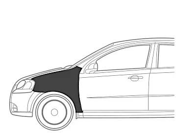
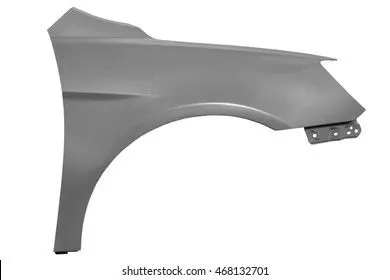
TYPES
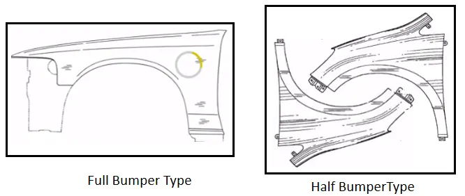
FULL BUMPER TYPE
This type of bumper is not commonly used because this design is more scrap producing one during manufacturing. The blank of steel or aluminum used to produce this type has more wastage. This type is not economically good to manufacture. Also it increases the material cost unavoidably. If we use full bumper type the material has to be either aluminum or steel, since these materials were generally used for fenders. This extension of material usage in bumpers might increase the proportion of weight and consequently reduce the performance of vehicle. Nowadays plastic material components are in use for bumper making. Plastics have high tendency in absorbing the shock and impact loads. And being light in weight it is easy to mount them on chassis.
HALF BUMPER TYPE
This is the most commonly used typed of fender. The con’s of full bumper type is satisfied in this design, and the blank area of wastage while producing the part is drastically reduced by scrap management. In this type by slightly increasing the blank size 50% of wastage is reduced by making two fenders on a same single blank of steel or aluminum. Also this design provides space for using plastic components in the bumper. Thus facilitating way for reducing a high proportion of weight and increase the vehicle’s performances significantly.
FENDER DESIGN
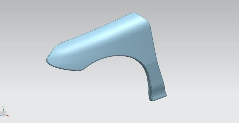
The fender is designed from the given styling panel. The fender needs the design of mounting areas on it. These mounting areas are common for almost all vehicles. But their mounting design is varied according to the requirement and mounting constraints. By using these mounting areas the fender is positioned in the vehicle using screws and bolts.
Given skin data:
Design constraints:
- Whatever embosses produced for the mounting areas it must possess flat surface. The embossed surface cannot possess any minimum radius of curvature. The presence of curvature is not desired because this might lead to damage that part while fixing the fender on vehicle.
- There should not be presence of any corners less than 2.5mm radius of relief. This is considered for pedestrian safety and manufacturing feasibility. The design can’t have any sharp corners which is not desirable.
- The edge blend used has to be >= 0.75mm. The edge blend radius can’t be lesser than 0.75mm.
- The face blend used has to be >= 0.75mm. The face blend radius can’t be lesser than 0.75mm.
- The hole strike on the embosses must possess a minimum distance of 3t i.e. 3*0.75 = 2.25mm from the edges of the embosses.
MOUNTING REGIONS OF FENDER
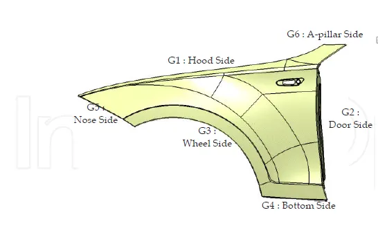
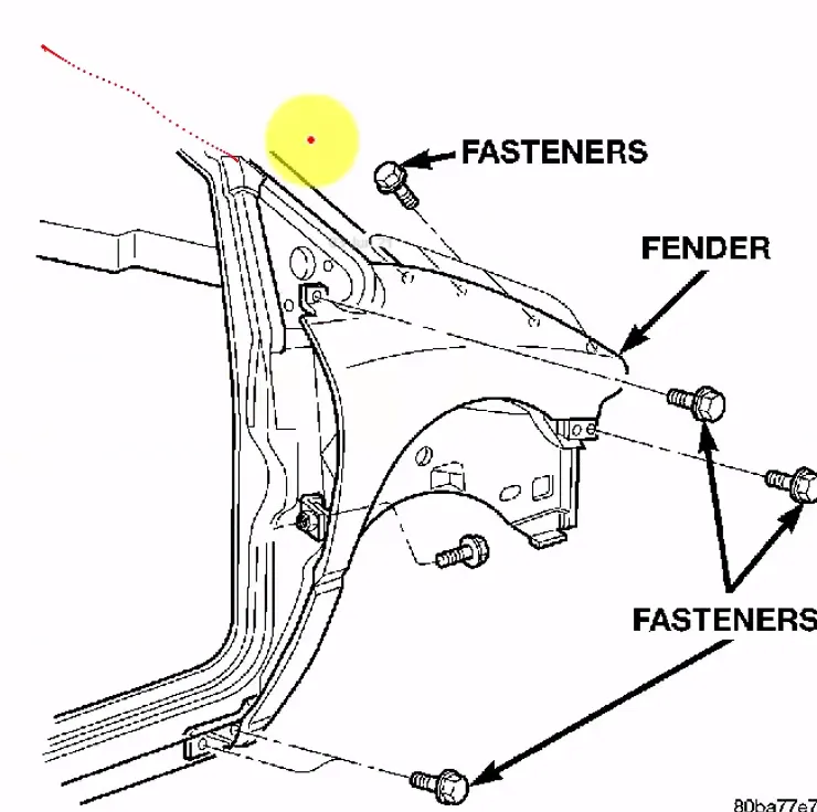
Mounting regions
There are five mounting regions to design
- Drip
- A – pillar
- Sill
- Cowl
- Body
Generally fasteners used to mount fenders onto the vehicle. The drip areas has the master sketch to follow up.
DRIP AREA MASTER SKETCH
Drip area has some design constraints which can be inferred from the master sketch. This drip area is the joining piece of fender and engine compartment.
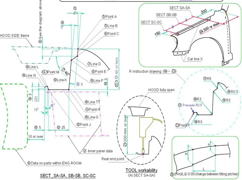
Master sketch of drip area
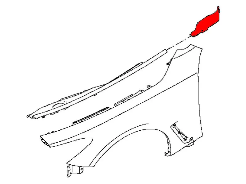
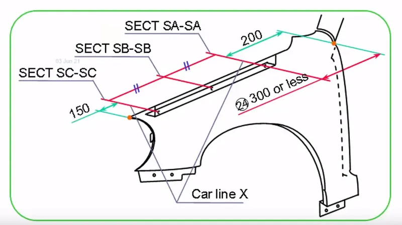
Drip area constraints
The drip area is given minimum 200 mm distance from the rear or 300mm less from the A – pillar of the car. This distance is given for wiper motor placement. Likewise a 150mm distance from front end of fender is given for the placement of head lamps housing unit. The remaining area is available for the drip design.
Master sketch interpretation:
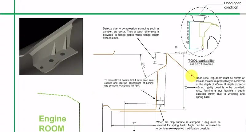
Master sketch info
- There must be a minimum of 10mm clearance from the trailing edge of drip to the engine room.
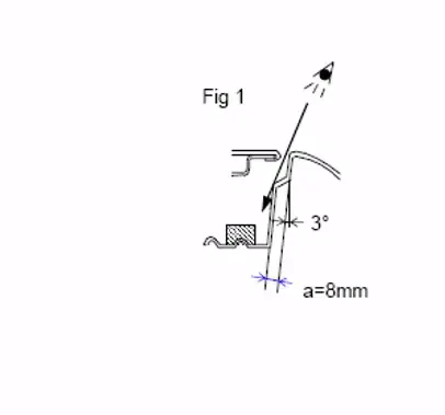
- There are three flanges which opens the drip. Two of them having an opening angle of 3degrees for the workability of the tool during drawing operation and also given as a spring back compensation. While the other flange is having 30degree inclination about flange1 by bending.
- The fender is mounted after hood is placed. Therefore after fully opening the hood the distance between drip area and hood ha to be 200mm minimum for better workability during welding and other operations.
- Predetermined flatness clearance of 1mm is given for the bracket surface of drip area.
- The depth of drip has to be 40mm or less, if the depth exceeds 40mm then beads, gussets, darts have to be given for the rigidity maintenance. Maintaining 40mm results in higher productivity. Exceeding 60mm can cause failure of forming operation due to wrinkling and spring back effect.
- The 3degree inclination also acts as a visibility shield from bad surfaces resulted during weld nuts operations.
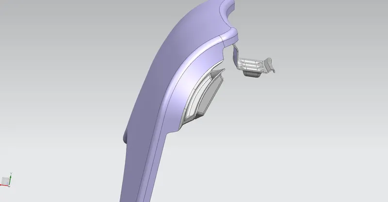
DRIP AREA
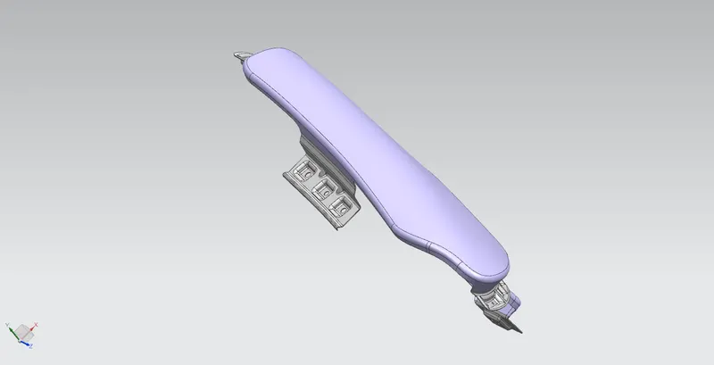
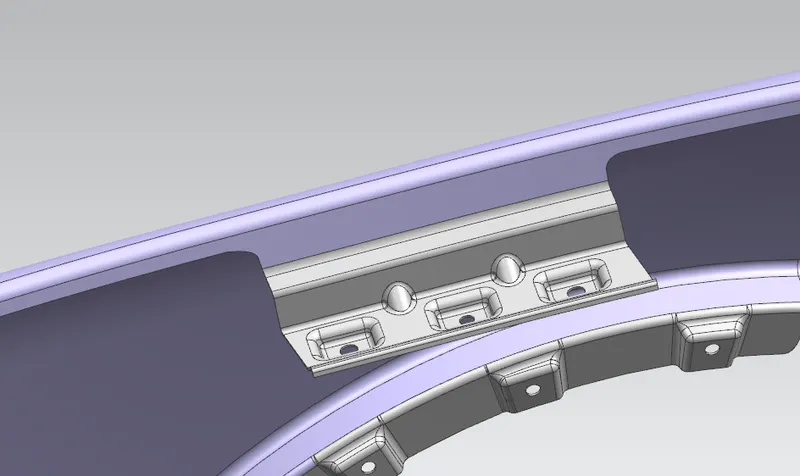
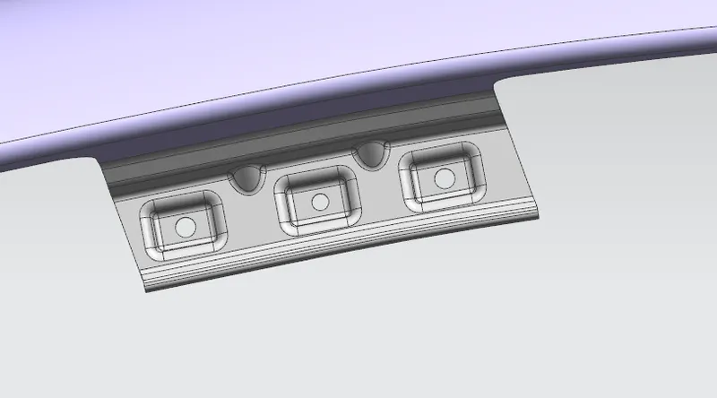
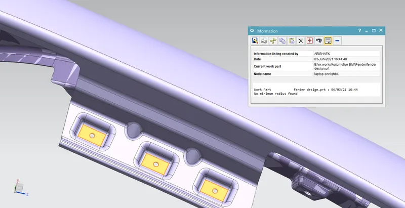
The emboss should not possess any minimum radius of curvature.
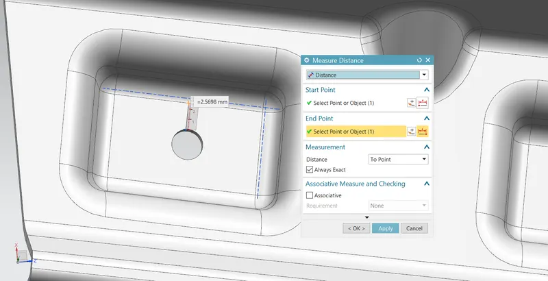
The minimum distance between the edges and the holes is 2.25mm.
A – PILLAR
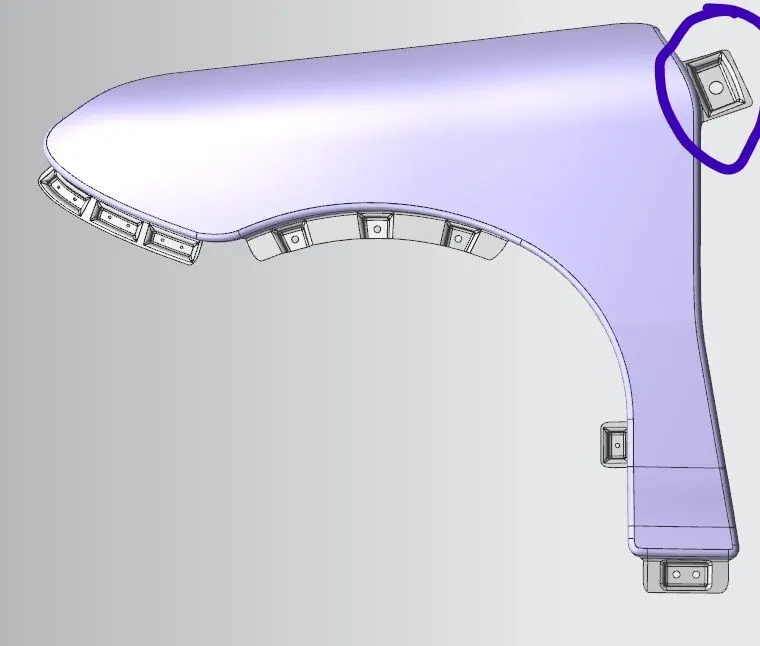
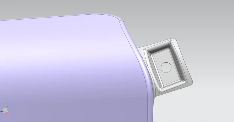
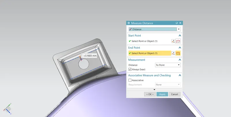
The minimum distance between the edges and the holes is 2.25mm.
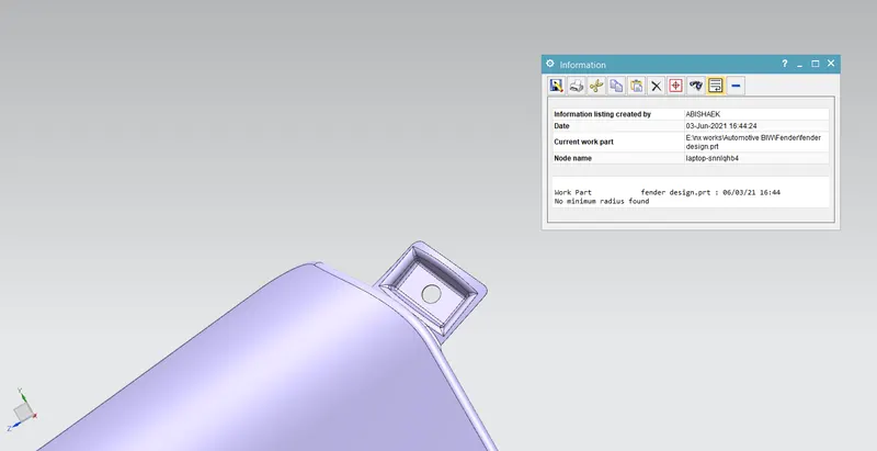
The emboss should not possess any minimum radius of curvature.
SILL
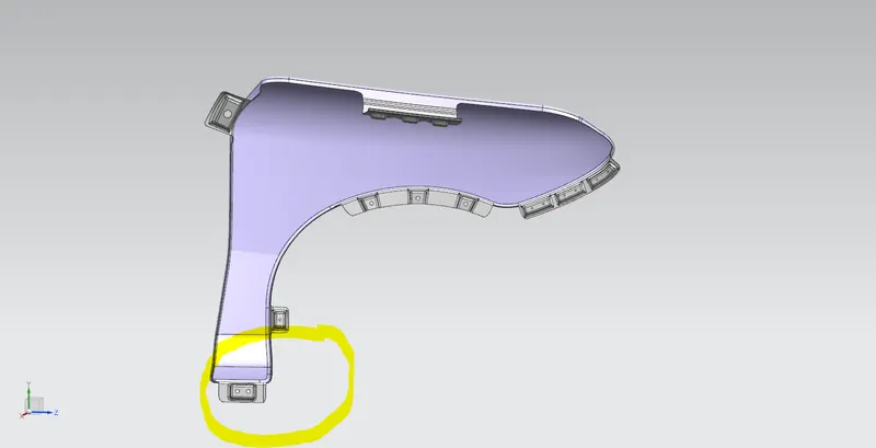
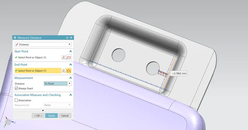
The minimum distance between the edges and the holes is 2.25mm.
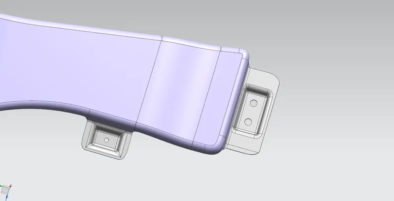
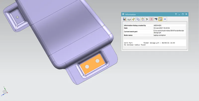
The emboss should not possess any minimum radius if curvature.
COWL
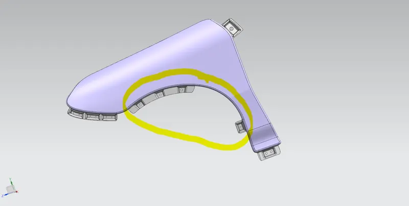
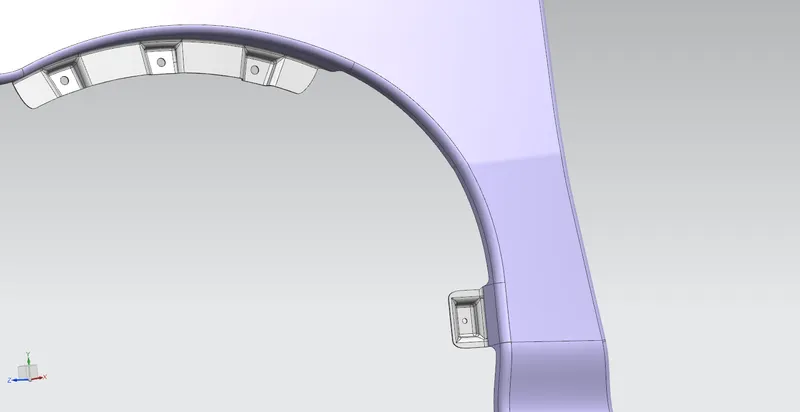
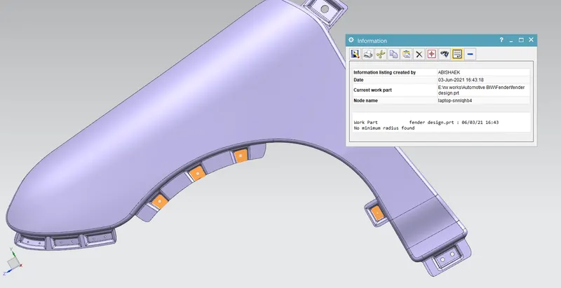
The emboss should not possess any minimum radius of curvature.
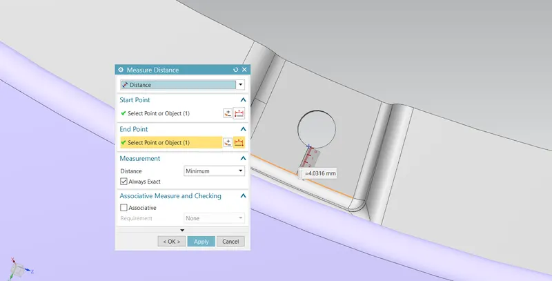
The minimum distance between the edges and the holes is 2.25mm.
BUMPER
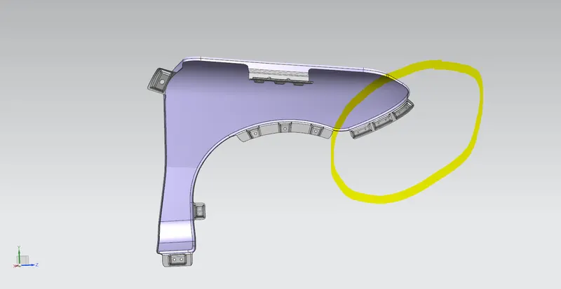
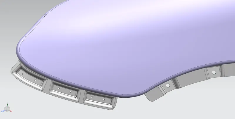
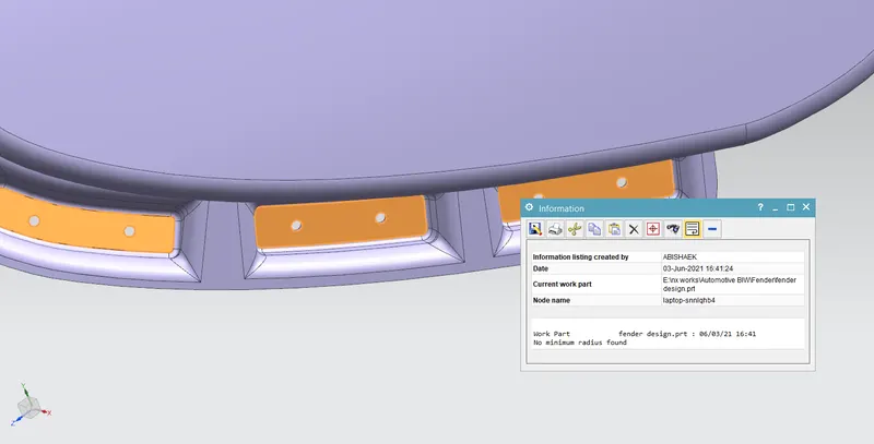
The emboss should not possess any minimum radius of curvature.
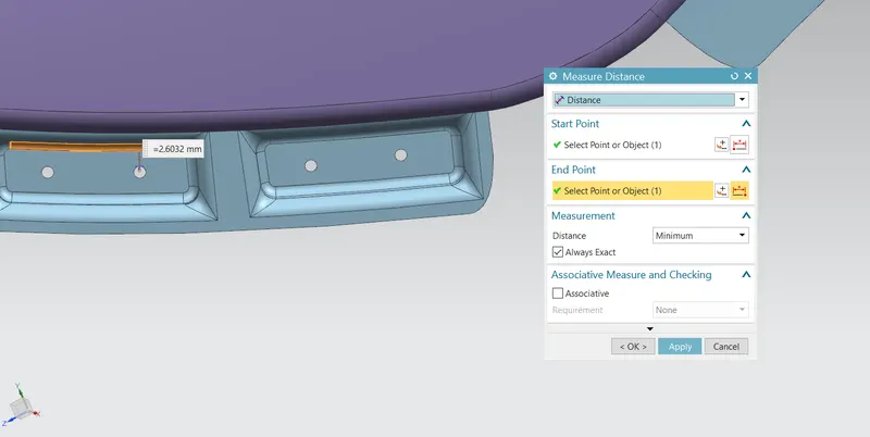
The minimum distance between the edges and the holes is 2.25mm.
FENDER
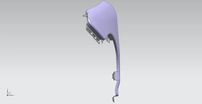
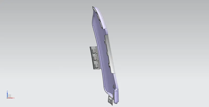
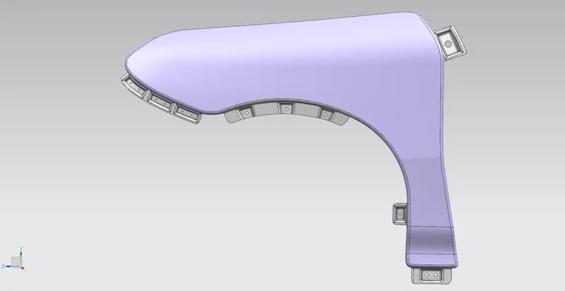
VALIDATING FENDER WHEEL ARCH AREA BASED ON EUROPEAN STANDARDS
The wheel arch study is classified based on different country zones. These zones like Japan, Europe and U.S have their own standards. The tire of the car does chipping dirt’s, grits or any other harmful metallic pieces onto the pedestrians and upon the car itself. To minimize this effect the wheel has to be completely placed inside the curvature of the fender. This study is done by a fender engineer immediately after receiving his styling panel of fender. By doing this study the fender’s class A surface is validated for wheel arch area.
EUROPEAN standard
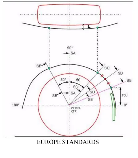
- From the wheel center two lines were taken at 30 degree (SB) and 50 degree (SC) from vertical axis.
- Take another line 150mm from the horizontal axis and extend it up to the fender (SE).
- Bisect the SE and SC line and make another line (SD).
- Now there are 5 sections of lines – SA, SB, SC, SD and SE.
- Project the front view of intersection points onto top view.
- Measure the clearance in between the point deduced from the lines on wheel and the corresponding normal point in fender. This clearance has to be 10mm or more. Measurement is done in the top view.
VALIDATING THE WHEEL ARCH
This study in done on the front fender of the automotive.
Criteria to satisfy the European standards –
- The clearance value for all the five sections has to be 10mm or more.
- For wheel guard requirements the clearance can be 5mm or more at the line 30 degrees forward and 50 degrees rearward from the central vertical axis.
- The tire face is considered as plane of sketch.
WHEEL ARCH STUDY SETUP as per EUROPEAN STANDARD
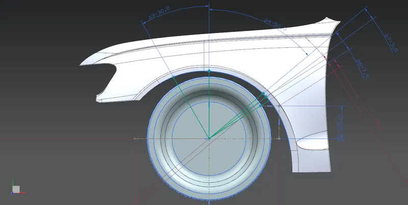
LINE SB 30 DEGREES FORWARD
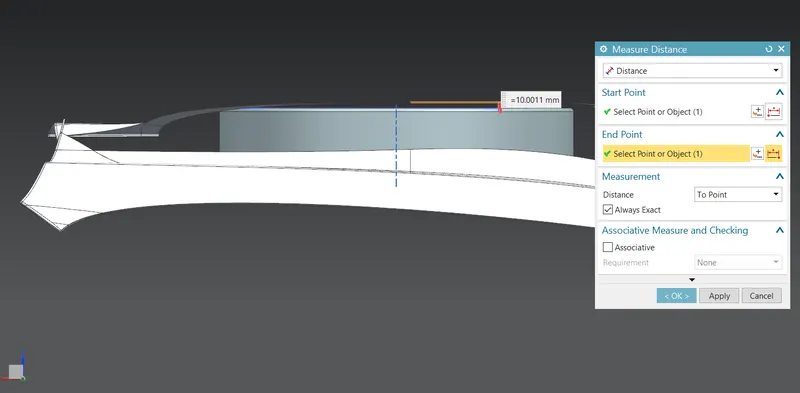
Inferred clearance = 10.0011mm
LINE SA VERTICAL CENTRAL AXIS
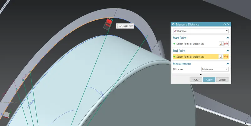
Inferred clearance = 9.9489mm
LINE SC 50 DEGREES REARWARD
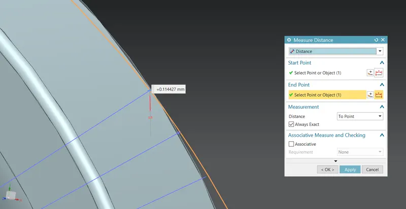
Inferred clearance = negative 0.114427mm
LINE SD
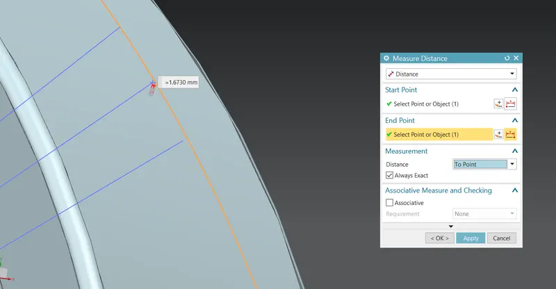
Inferred clearance = negative 1.67mm
LINE SE 150MM OFFSET FROM HORIZONTAL AXIS
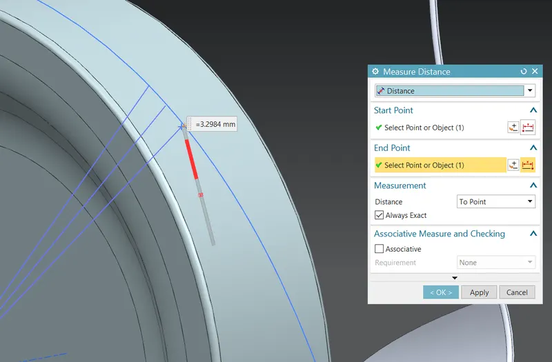
Inferred clearance = negative 3.2984mm
RESULT OF VALIDATION OF WHEEL ARCH AREA
| S.no | SECTIONS | Required CL value (mm) | Measured CL value (mm) | Result of validation |
| 1. | SB | >=10 | 10.0011mm | PASSED |
| 2. | SA | >=10 | 9.9489mm | FAILED |
| 3. | SC | >=10 | - 0.114427mm | FAILED |
| 4. |
SD |
>=10 | -1.67mm | FAILED |
| 5. | SE | >=10 |
-3.2984mm |
FAILED |
CONCLUSION
The fender is designed with the required mounting regions.