Fender Design Challenge
FRONT FENDER DESIGN (BIW)
we can say the fender is an automobile part that protecting the engine compartment and pedestrians from stones hitting, rainwater projection, and also on.
it is providing a better look to the car and during the collision, the fender will absorb the energy so passenger safety will be Assured.
this way of perspective design will ensure pedestrian safety from hitting by a car.
basically, there are two types of the fender
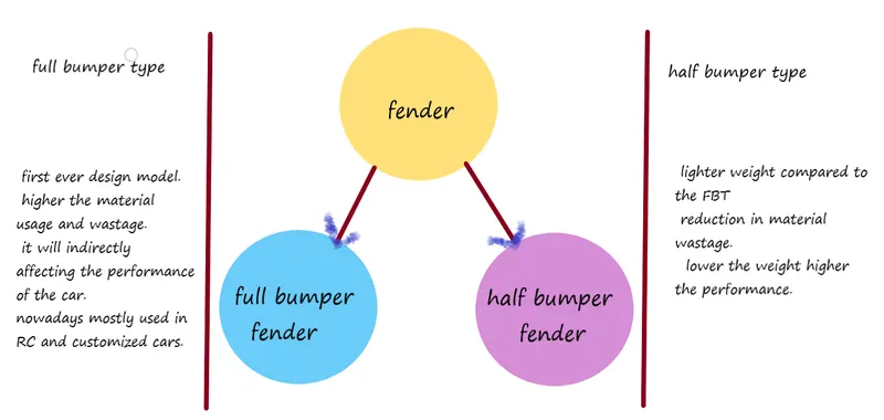
- full bumper type
- half bumper type
full bumper type
As the name suggests full bumper type will cover a larger area compared to the half bumper type.
the full bumper type nowadays is not highly used because it has a larger sheet metal area, so the cost of the vehicle increased and the weight too.
but some of the cases it is still in use like RC signature cars

Half bumper type
here almost half of the material cutouts from the full bumper type.
it is one that kind of evolved from the full bumper. materials are reduced so the cost and weight of the car will also be reduced.
The lighter the weight of the car higher the performance. related pics are given below
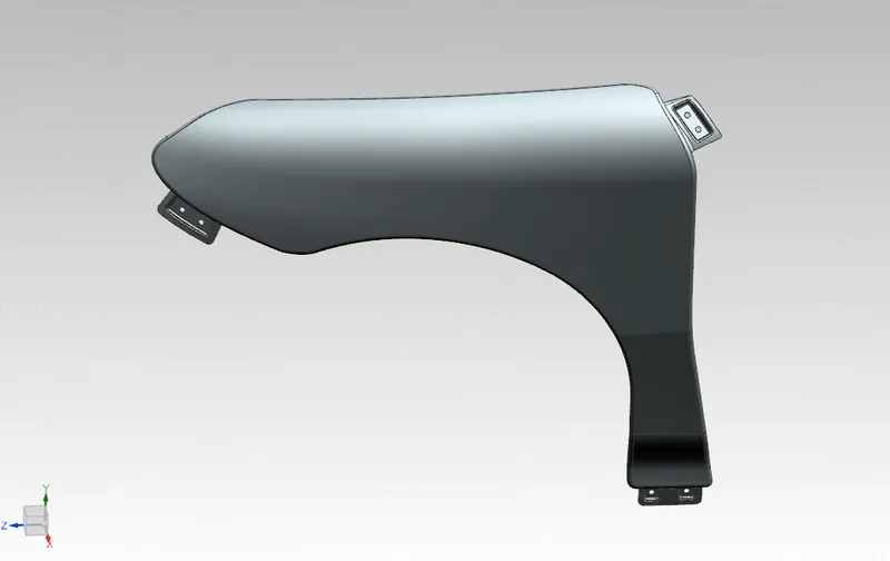
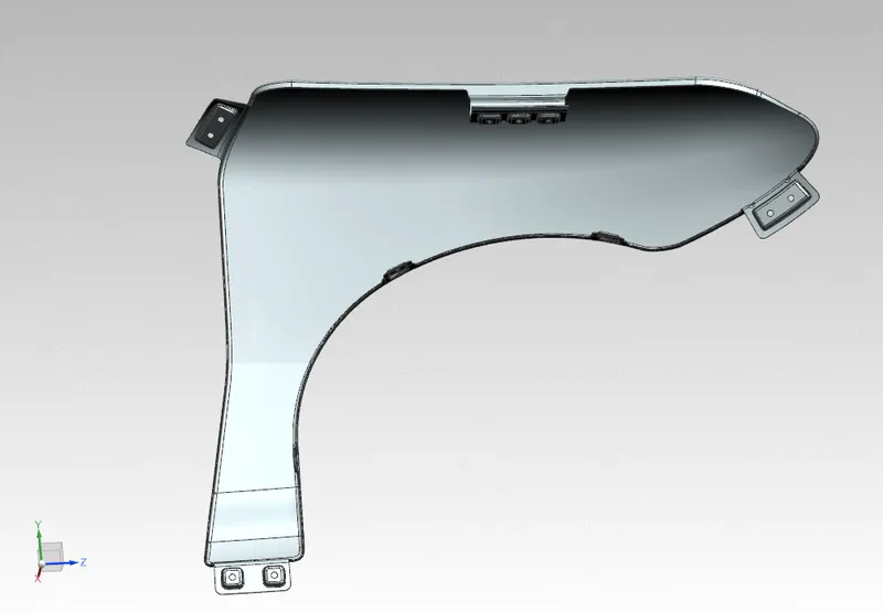
areas that we should concentrate on while designing a fender
1.drip area mounting
2.wheel arch area
3.A Piller area mounting
4.bumper mounting
5.sill area mounting
6.cowl area mounting
1. Drip area mounting
The drip area was designed by the master section given to me.
master section
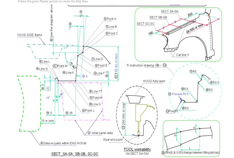
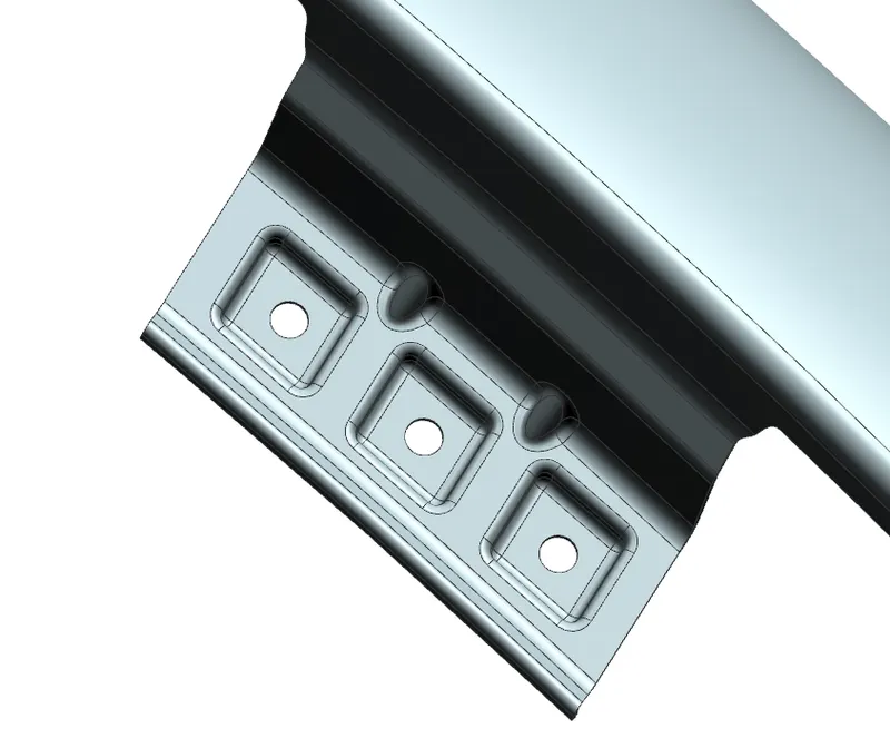
the hole sizes are 5 mm. and the emboss was created to improve the strength of the sheet metal.
designing the drip area following the master section ensures.
there is no spring-back effect.
enough space to fastening.
in the corners, stiffness has increased.
maximum space between the engine compartment and fender.
bend has been applied to all sharp corners. so the tool will be doing the operation smoothly.
A pillar area mounting
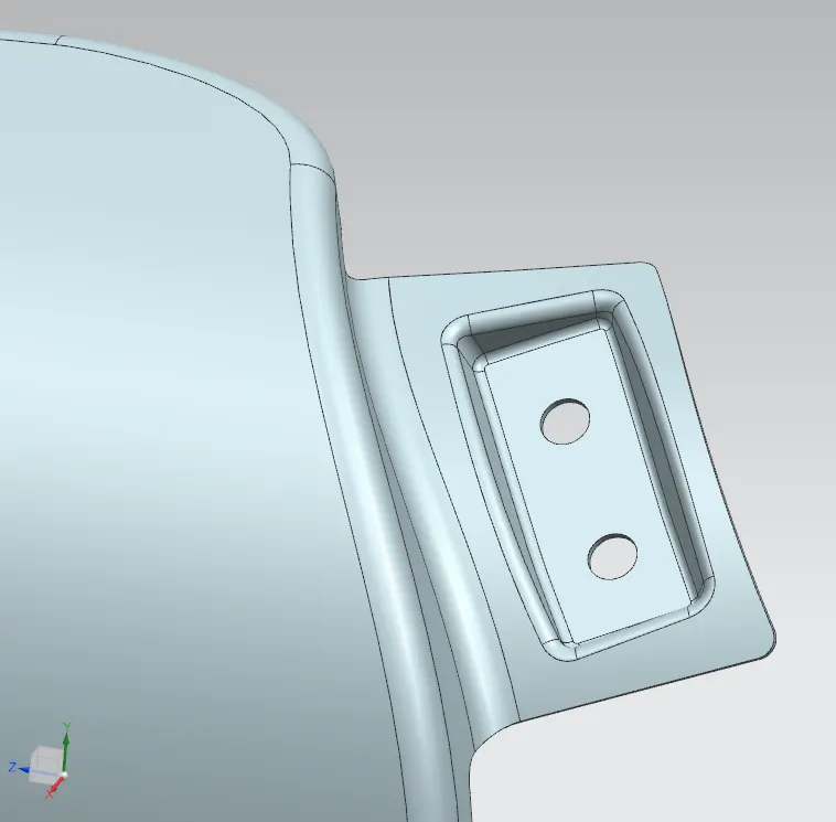
this is a pillar mounting area there are two holes made up to attach with a side pillar.
bumper mounting area
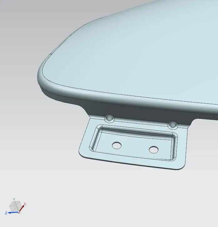
In the bumper mounting area, this is where the bumper will come and attach by fastening since the extension sheet has a little bit longer length I created a dart to reduce the vibration so the NVH will increase.
sill area mounting
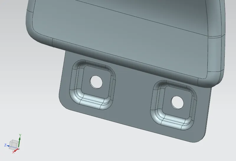
sill mounting area is the bottom-most area of the fender. after the fastening operation, a cover will be added in the bottom area to cover the fastening and all.
cowl mounting area
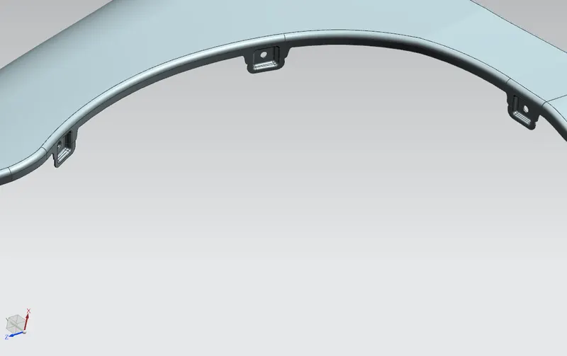
this is a cowl mounting area this is where the plastic guard will come and joined with the cowl mounting point.
design for manufacturing.
during the design process features are added the way which are manufacturable.
in the embossed area, there were draft angles provided 10 degrees to 15 degrees so the tool will in and out. and there were no sharp corners.
minimum of 10 mm radius flatted surface ensured from the center of a hole to make sure of perfect fastening operation.
since we are working on the sheet metal part some standards are followed to reduce the failure during the manufacturing. like
hole diameters are larger than the sheet metal thickness.
spacing between the holes should be at least double the times of sheet metal thickness.
FRONT VIEW OF FENDER
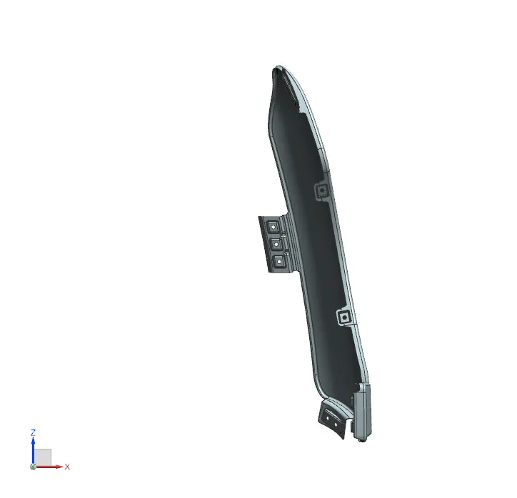
RIGHT SIDE VIEW
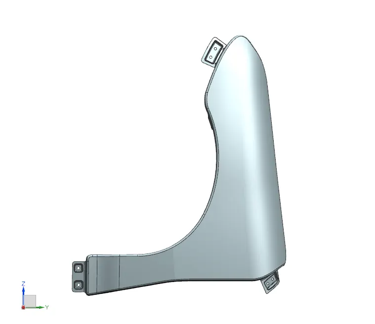
TOP SIDE VIEW
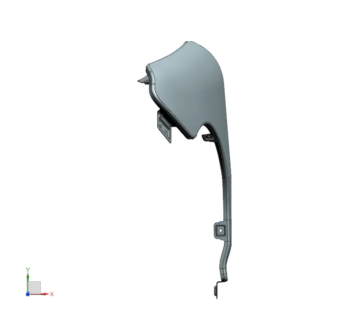
ISOMETRIC VIEW
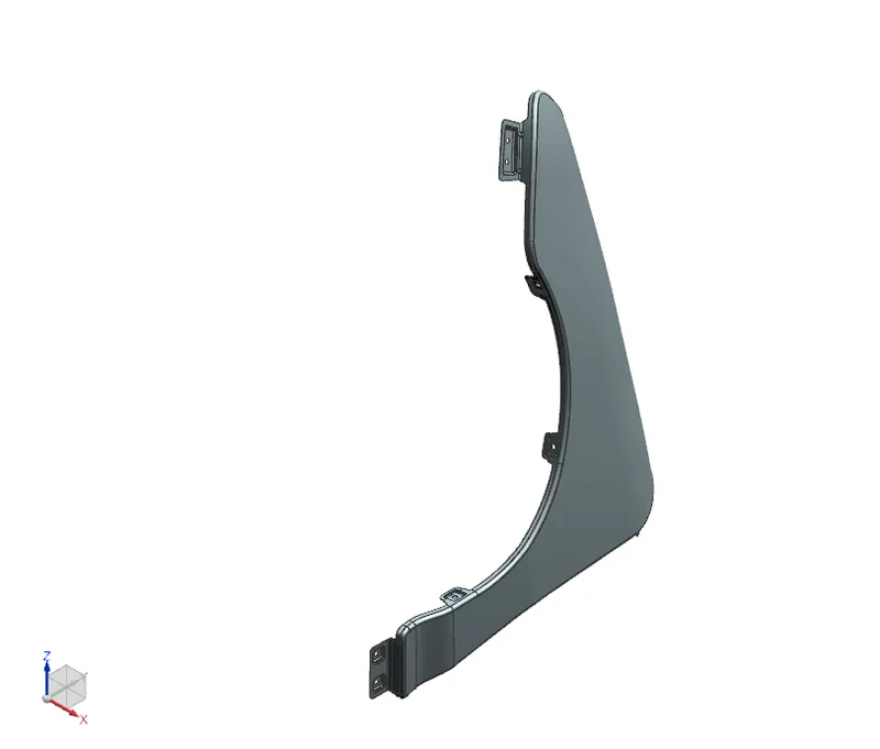
CONCLUSION
thus the front fender has been successfully designed by considering the master section and design standards.