Fender Design Challenge
Fender Design Using Siemens Nx
Objective:
The main objective is to design front fender of a car from given skin data and the master section using Siemens Nx application.
Introduction:
Here, we are going to study about how to create a Fender of a car by providing necessary mountings as per the requirement using siemens Nx Application. Using this application, how we are going to use tools step by step to complete the design. Then complete explanation about tools used to create fender and its safety considerations to be followed in designing a fender.
Fender:
Fender is the American English term for the part of an automobile, motorcycle or other vehicle body that frames a wheel well (the fender underside). Its primary purpose is to prevent sand, mud, rocks, liquids, and other road spray from being thrown into the air by the rotating tire. Fenders are typically rigid and can be damaged by contact with the road surface.
Sticky materials, such as mud, may adhere to the smooth outer tire surface, while smooth loose objects, such as stones, can become temporarily embedded in the tread grooves as the tire rolls over the ground.
These materials can be ejected from the surface of the tire at high velocity as the tire imparts kinetic energy to the attached objects. For a vehicle moving forward, the top of the tire is rotating upward and forward, and can throw objects into the air at other vehicles or pedestrians in front of the vehicle.
Types of Fender Designs:
There are different fender styles. While appearance may be one of the first things on a person mind when choosing a fender style, but one should also be thinking about the amount of coverage that will need to cover enough to stop water spray, rocks and other debris from hitting your truck, trailer and other vehicles on the road.
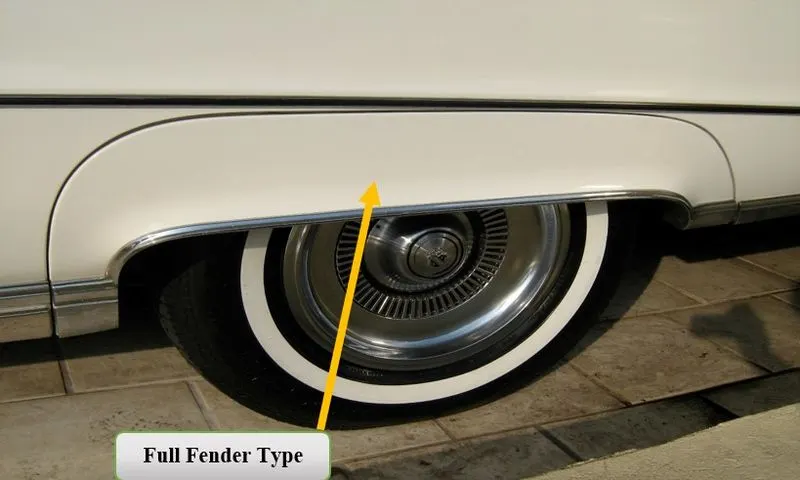
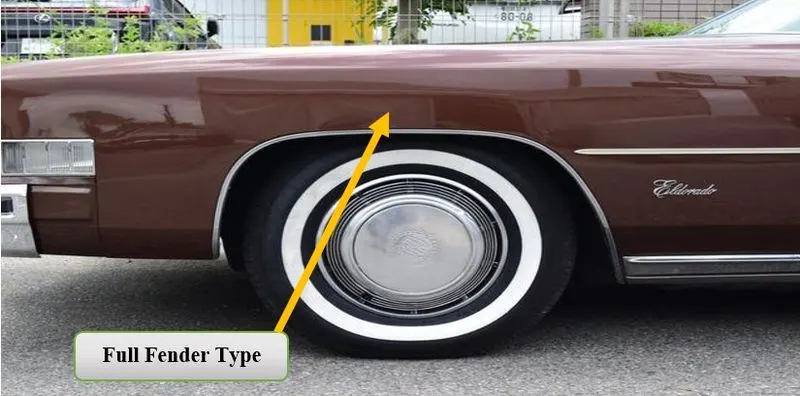
Full Fender Type:
A full fender means they will be covering more area around the wheel in comparison to the half fender type and also it extends towards the ground a lot more. The main advantage is increased coverage, less water on you and importantly less water on your feet, meaning less road dirt and stuff stays drier longer. Since, they cover more it also has the benefit of shielding your bike a bit more from gritty wearing road dirt so your bike components will also benefit. But, due to its bulky shape the full fender increases the weight of the component which in turn increases the overall weight of the car’s body.
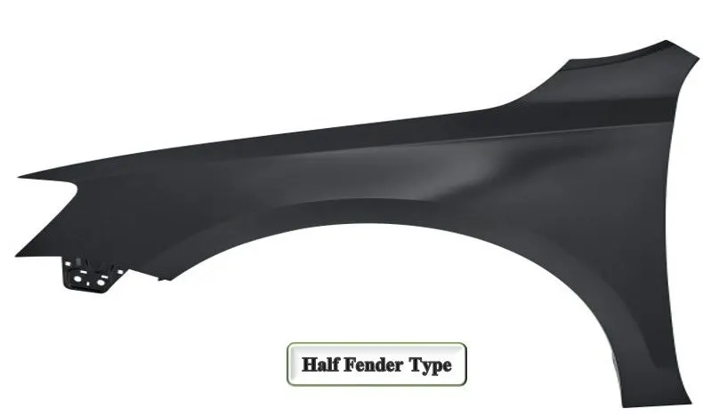
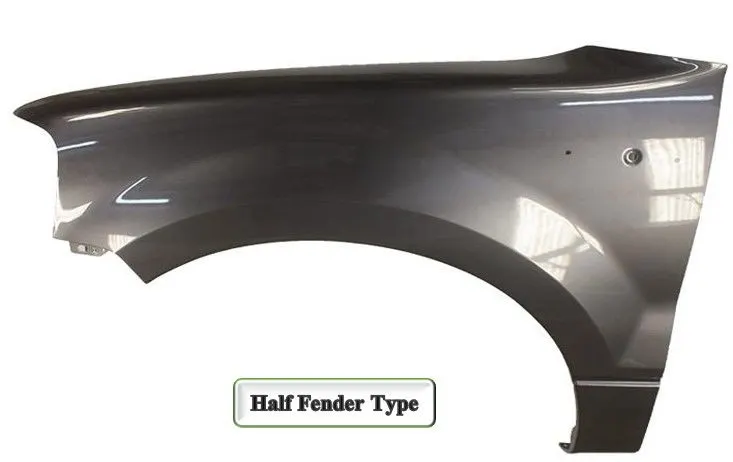
Half Fender Type:
As the name itself refer, the half fender will be covering only the half portion of the wheel’s area while the remaining part will be covered with the bumper part. This is done to make sure the weight of the vehicle is reduced without comprising on the quality & service. Most of the modern-day vehicles come with half fender because of their rich aesthetic finish & low overall weight.
Design Methodology:
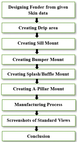
The design methodology of fender design is explained through flow charts.
Description:
Designing Fender from given Skin Data:
- Start Siemens Nx application to design fender. Opening a given skin data file.
- Clicking on the Part navigator tab, in that click on body to assign a feature group name as Parent File to secure design.
- Extracting the body in the parent file.
- Clicking on the offset surface icon the dialog box appears, in that select faces of skin data and offset to 0 mm. Then click ok to validate.
- Assigning Feature group name as Working File to the offset surface.
- Hiding Parent file and start designing on Working file.
- Clicking on Offset curve in face icon the dialog box appears, in that select curves to be offset, setting distance of 5 mm and selecting face of skin data. Then click ok to validate.
Creating Drip Area:
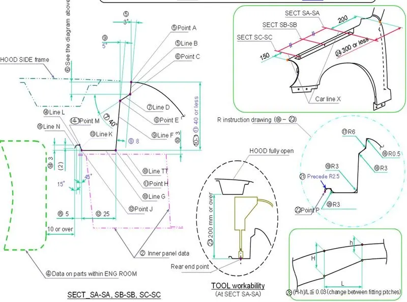
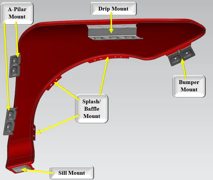
- Drip Area is the main part which needs to follow design requirements and constraints, because its to mounted to the engine compartment. Following the Master Sketch to create drip area.
Master Sketch:
Commands Used to Create Drip Area:
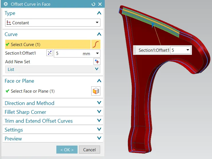
- Offset curve in Face: Used to offset curve to the required distance. Follow the steps as per the image attached below.

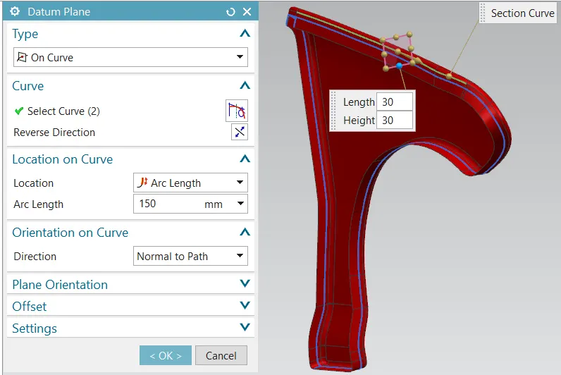
2. Datum Plane: Used to create new plane on the required place. Here datum plane are used to create intersection curves on the particular face to satisfy the master section parameters. Reference image is attached below.
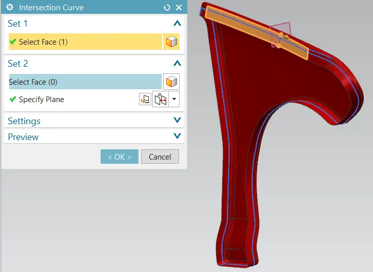
3. Intersection Curves: Clicking on the intersection curve icon the dialog box appears, in that select face and specifying plane. Then click ok to validate.
4. Redoing the above two steps (2 & 3) to satisfy the master section requirements by changing parameters.
5. Again, using offset curve in face command, in that select curve, offset parameter to 5 mm and select face. Then click ok to validate as per below attached image.
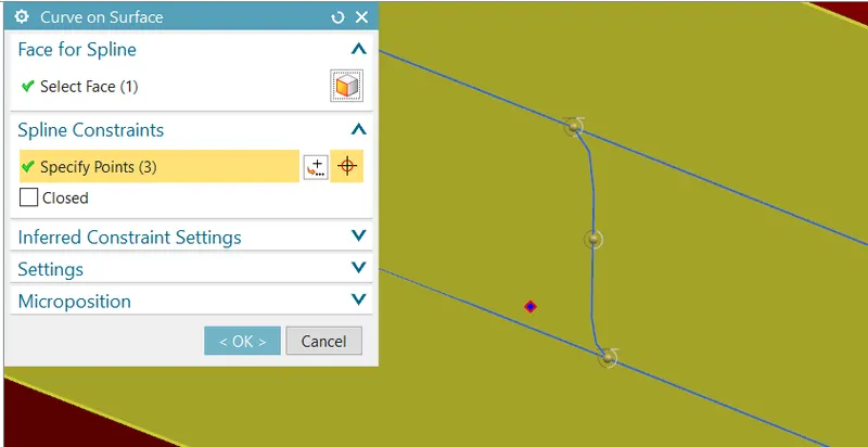
6. Curve on Surface: This tool is a powerful tool to create spline curve on the required place using three points. For the starting point & ending point needs to mention as G1(Tangent). Reference image as attached below and follow the steps according to it. Until wherever necessary.
7. Trim Sheet: Clicking on the trim sheet icon the dialog box appears, in that select sheet body as target, select object as boundary and select region to trim. Then click ok to validate.
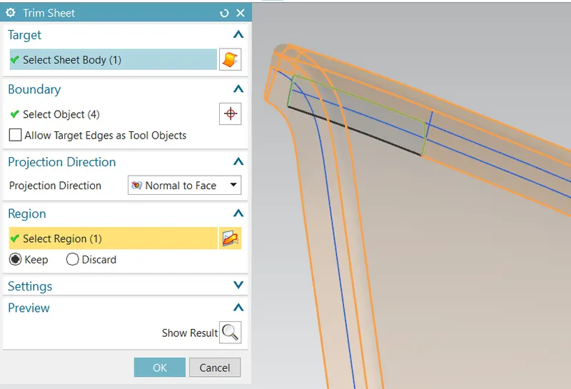
8. Redoing trim sheet steps to remove excess material around drip area.
9. Law extension: Clicking on law extension icon the dialog box appears, in that select type as vector, select curve and specifying vector to extend sheet, length law as 8 mm and angle law as 40 degree. Then click ok to validate.
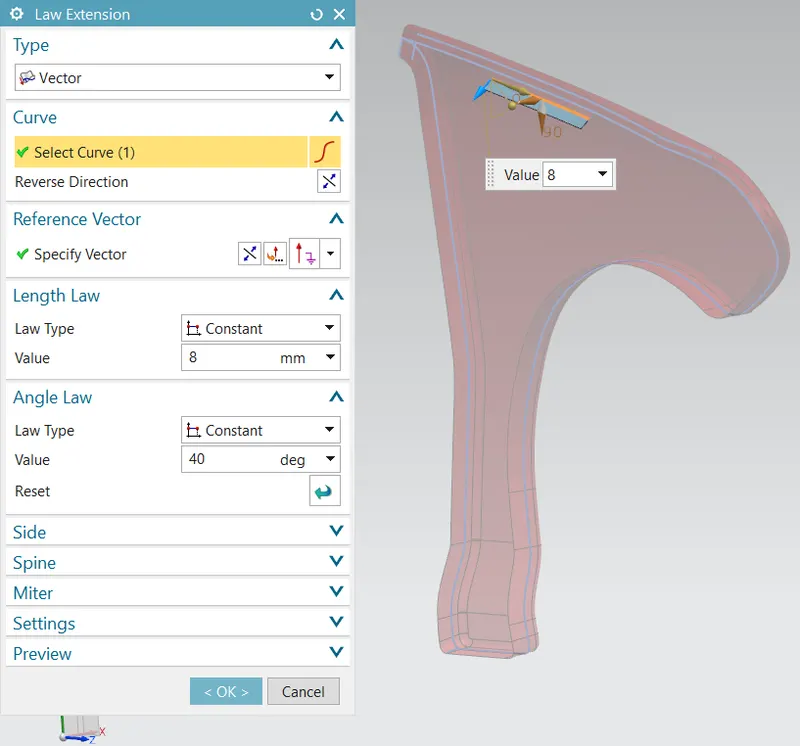
10. Redoing the law extension steps by changing parameters to satisfy the master section.
11. Face Blend: Clicking on the face blend icon the dialog box appears, in that select type as Two-Face, select face one and face two, set parameter as 6 mm radius. Then click ok to validate.
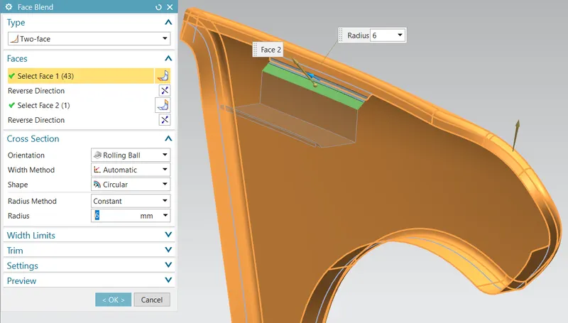
12. Redoing the same face blend steps, but changing the parameters as per the master section.
13. Sketch on the drip area to provide provision for emboss the sheet to mount on the engine compartment. Project the sketch on the required surface to create emboss.
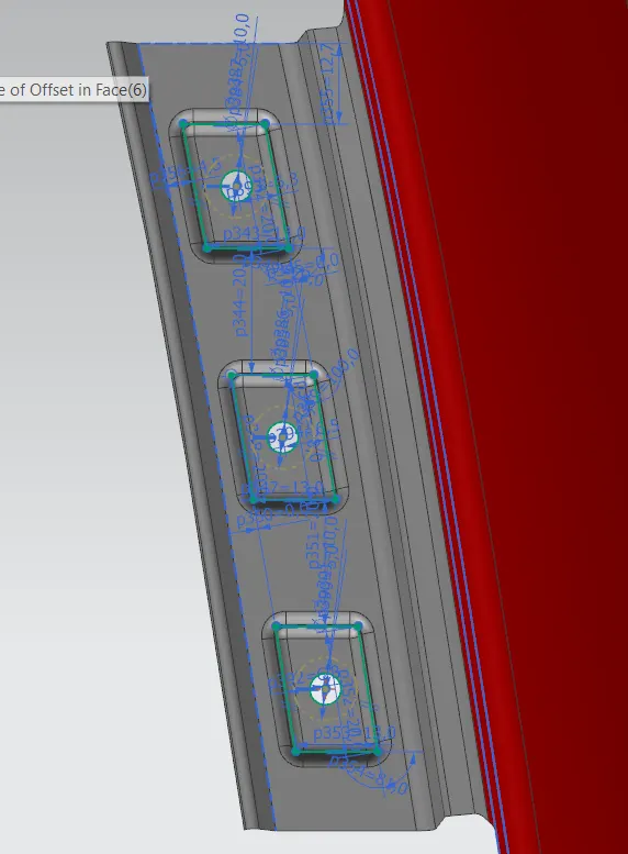
14. Project Curve: This command is used to project the drawn sketch to the required face.
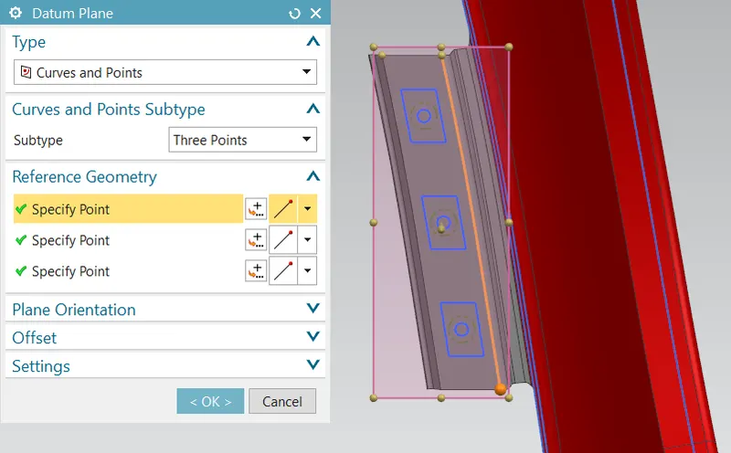
15. Datum Plane: Clicking on this icon the dialog box appears, in that select type as Curves & Points and select three points on a surface were the plane needs to create.
16. Emboss: Clicking on this icon the dialog box appears, in that select sketch curves, select face to emboss, specify emboss direction, select End cap geometry as datum plane, select datum plane, specify offset distance as 3.5 mm and setting an angle of 15 degree. Then Click ok to validate.
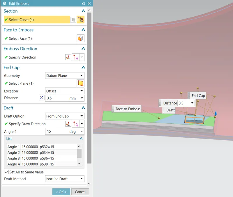
17. Redoing the same emboss steps to the remaining drawn sketches to complete emboss feature.
18. Trim sheet command is used to create holes in the embossed face which is already created on the sketch.
19. Edge Blend: This command is used to blend sharp corners. Clicking on the icon the dialog box appears, in that select edges from embossed faces and set radius of 2 mm. Then click ok to validate.
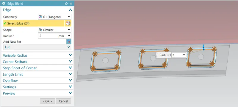
20. Face Blend: Clicking on the face blend icon, select type as Two-Face, select face one & face two to blend at the radius of 2 mm. Then click ok to validate.
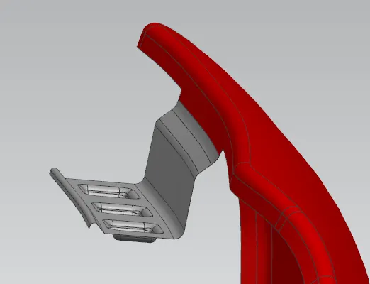
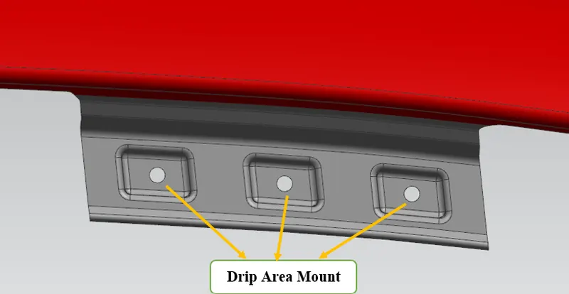
Drip Area Views:
Side View:
Top View:
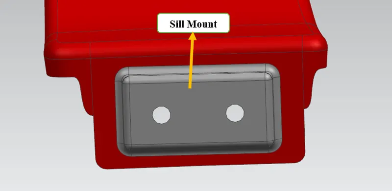
Creating Sill Mount:
- The Following commands were used to create sill mount.
- Curves on Surface, Trim sheet, extend sheet, Datum Plane, Sketch, Emboss, Edge blend, Face Blend and Bridge curve.
- The above commands were following the same procedures followed for drip area, but changes in parameters.
Sill Mount View:
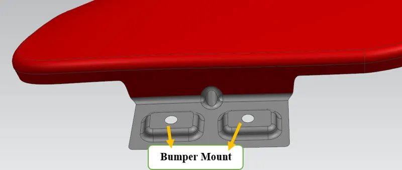
Creating Bumper Mount:
- The following commands were used to create bumper mount.
- Law Extension, Datum Plane, Sketch, Project Curve, Emboss, Edge blend, Trim sheet, Sew, Dart.
- The above commands were following the same procedure as sill mount, but the parameters are changed according to the requirements.
- The Dart command is used to stiffen the bumper mount to improve NVH.
Bumper Mount View:
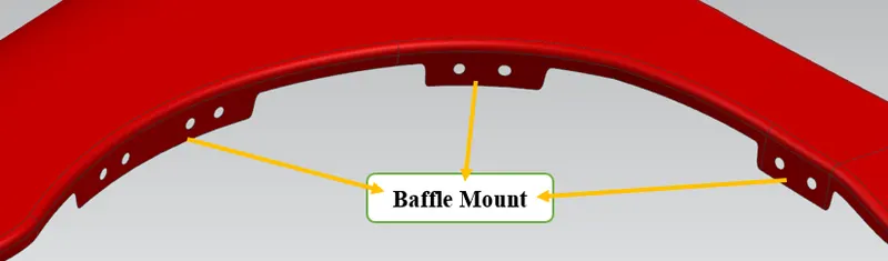
Creating Splash/Baffle Mount:
- The following commands were used to create Splash/Baffle mount.
- Datum Plane, Sketch, Project Curve, Trim sheet.
- The above commands were following the same procedure as above mounts, but the parameters are changed according to the requirements.
- Here only 5 mm holes were created to mount baffle with fasteners.
Baffle Mount View:
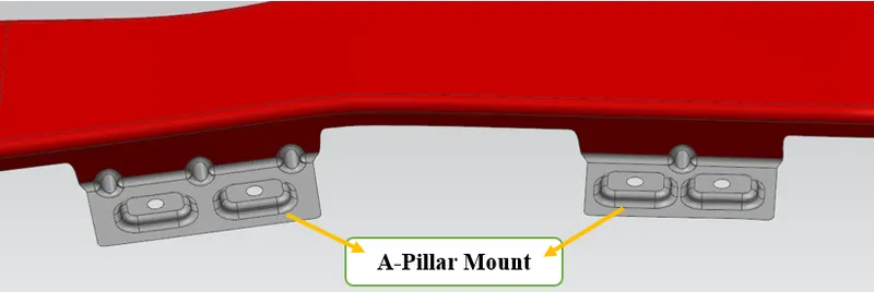
Creating A-Pillar Mount:
- The following commands were used to create A-Pillar mount.
- Law Extension, Datum Plane, Sketch, Project Curve, Emboss, Edge blend, Trim sheet, Sew, Dart.
- The above commands were following the same procedure as Bumper mount, but the parameters are changed according to the requirements.
- The Dart command is used to stiffen the bumper mount to improve NVH.
A-Pillar Mount View:
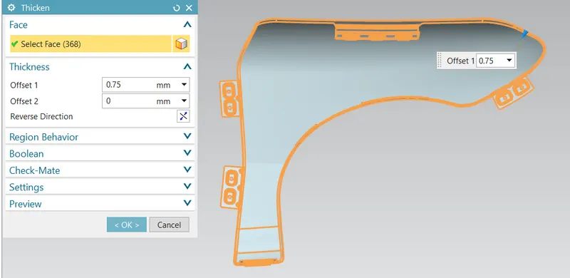
Thicken:
- Clicking on the thicken icon the dialog box appears, in that select faces and offset thickness as 0.75 mm. Then click ok to validate.
Thicken View:
Manufacturing Process:
A Vehicle Fender monitor is made by an interaction called Reaction Injection Moulding (RIM), which basically includes making a one-of-a-kind polyurethane compound and bringing it into an immense fender. RIM is a methodology that screens unrefined materials and lessens costs. It resembles injection moulding beside thermosetting polymers are used, which requires a re-establishing reaction to occur inside the shape. Normal Things made through RIM join vehicle monitors, air spoilers and fenders.
Screenshots of Standard Views:
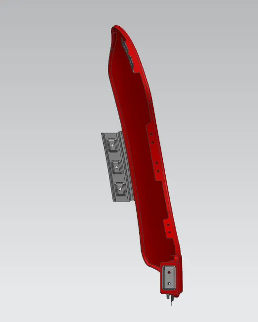
Front View:
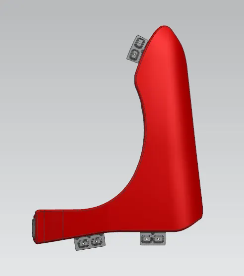
Right Side View:
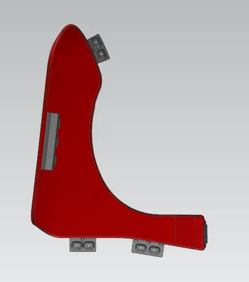
Left Side View:
Top View:
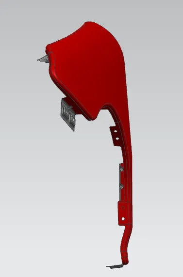
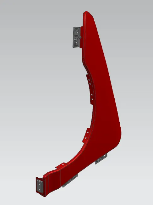
Isometric View:
Detailed View:
Conclusion:
Finally completed the Fender Design using Siemens Nx application as per the Master sketch and design parameters provided to complete design.