Fender Design Challenge
AIM:
DESIGNING THE FRONT FENDER OF THE CAR IN UGNX CAD
OBJECTIVE:
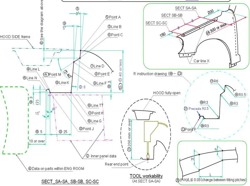
The objective of the design is to produce a BIW of the front fender of the car with its mounting using the information provided by the styling team such as skin data, master sketch information
INTRODUCTION :
fender is the American term used for an automobile part whose main purpose is to prevent engine compartment from outside debris, sand, mud, liquid on the road. materials like mud and small pebbles can get stuck in the wheel threads. these materials can be ejected from the tire surface at a very high velocity to the front or back side depending upon the rotation of the wheels, fender protects the nearby compartments from these materials.
TYPES OF FENDER :
- FULL-FENDER
- HALF FENDER
MASTER SECTION :
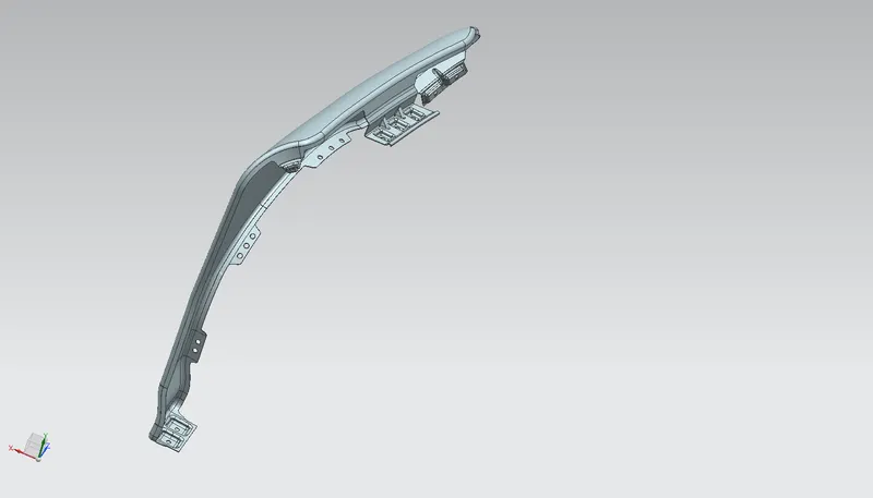
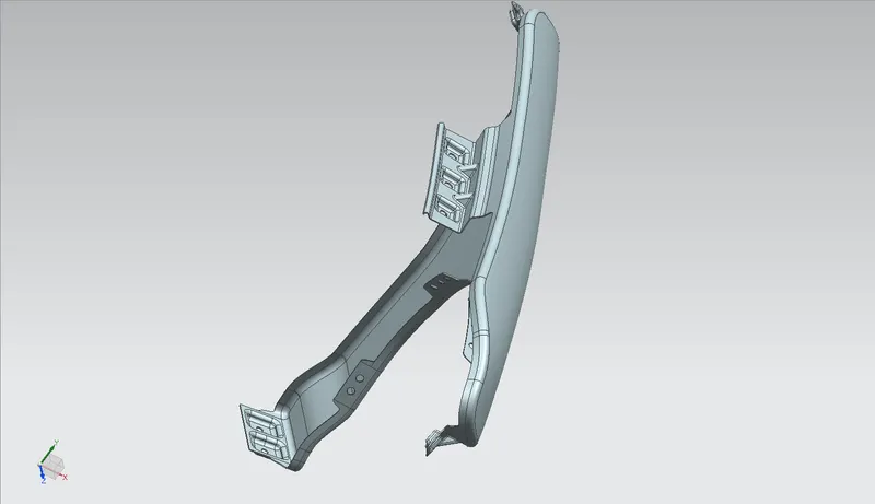
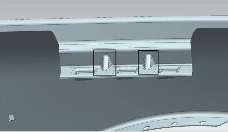
DESIGNING THE DRIP MOUNTING
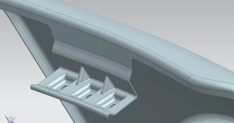
- designing of drip also plays an important role in hiding the inside of the car which can be seen through the gap between the fender and hood
- by using the information from the master sketch drip area was created
- from the front end, a distance of 150mm should be given
- from the back end, 200mm (300mm or less) should be given
- for creating the drip area at the required distance two planes were created and the using intersection curve command two curves were created on the surface
- using the data from master sketch drip area was created at a particular angle
- using law extension, extensions were created, and then required emboss were created
- a datum was created using 3 point method and then a sketch was created corresponding to that datum
- emboss were created for the sketch on the plane along the vector using emboss command
- using trim sheet fastener holes were created
- required blends using face and edge blends were created
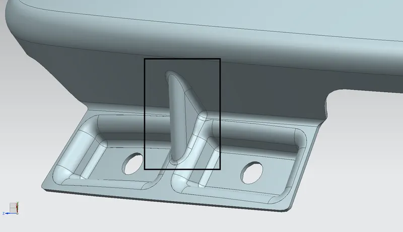
- for improving stability and reducing NVH at the drip area a rib/dart was created using the dart command
DESIGNING THE SILL MOUNTING
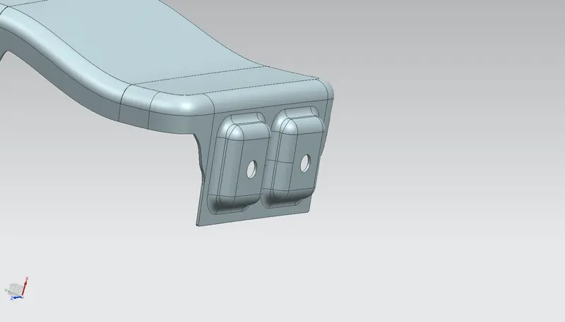
- Initially, the extra portion was trimmed out
- datum was created using 3 point method and a sketch was created corresponding to it
- the emboss were created and the edges were blended together
- fastener holes were created using the trim sheet command
DESIGNING THE A - PILLER MOUNTING
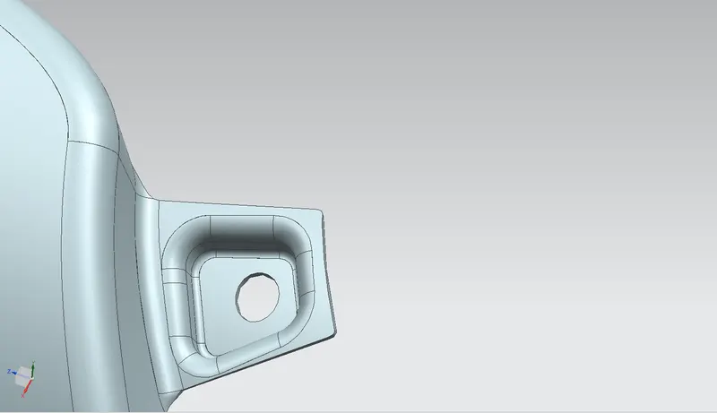
- the outer edge of the fender is offset to a particular length then by the curve on surface command curves were generated and the then unwanted area was trimmed off
- by using the law extension edge was extended to obtain a straight surface
- to get a flat to emboss a datum was created using the 3point method and then sketch was created corresponding to that datum
- the sketch was projected on the surface along the vector and then emboss was created
- using trim sheet fastener hole was created and the sharp edges were blended together using face blend and edge blend
DESIGNING THE BUMPER MOUNTING
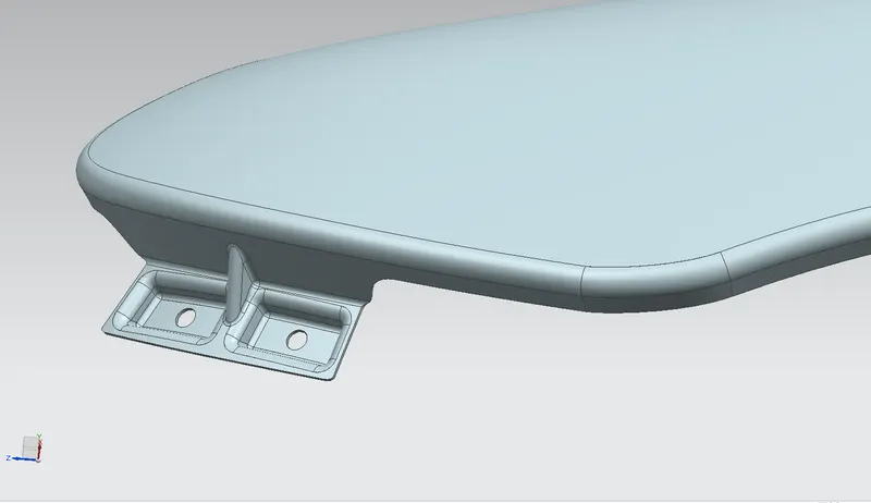
- Initially, the unwanted material was trimmed off using the curve on surface command
- then in order to create a flat emboss we first have to make a datum plane at that surface using 3 point method and then make a sketch corresponding to that datum plane
- project the sketch along the vector on the surface
- fastener holes were created by trimming the surface using the timesheet option
- emboss was created and required blends were given using the face and edge blend option
- for improving stability and reducing NVH at the drip area a rib/dart was created using the dart command
DESIGNING THE COWL MOUNTING
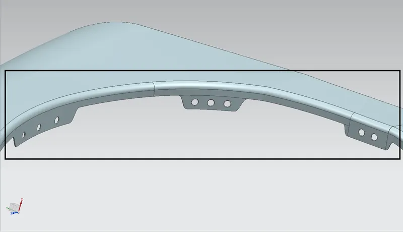
- Cowl mounting is used to fit a splash mounting on it
- initially, 3 mounting areas are created using a curve on surface and trim sheet option
- for creating holes sketch, the datum was created using 3 point method and a sketch was created corresponding to it
- for creating the fastener holes trim sheet option was used and the sketch was a project along the vector on the surface
THICKNESS: the thickness of 0.75 is given to the fender part
CONCLUSION :
The BIW fender part was created in NX cad using the master sketch and engineering standards.