Fender Design
Fender Design:
Fender:
Fender is a curved panel that protects the car from debris, dirt and rocks from the road that may cause chipping inside the engine compartment. Fender helps to protect the tires of the car. It also helps to protect the pedestrians from the mid and other debris that flies into the air. Fenders are made from plastic or metal.
Fenders are of two types:
1. Full bumper type fender:
A full bumper type fender is a traditional fender that extends across the entire width of the front of the vehicle and is often incorporated into the bumper. It is not being used in recent times because of the high amount of material that it requires to be manufactured. It also leaves behind a lot of scrap material. Full bumper type fenders are also quite heavy which reduces the fuel efficiency of the vehicle.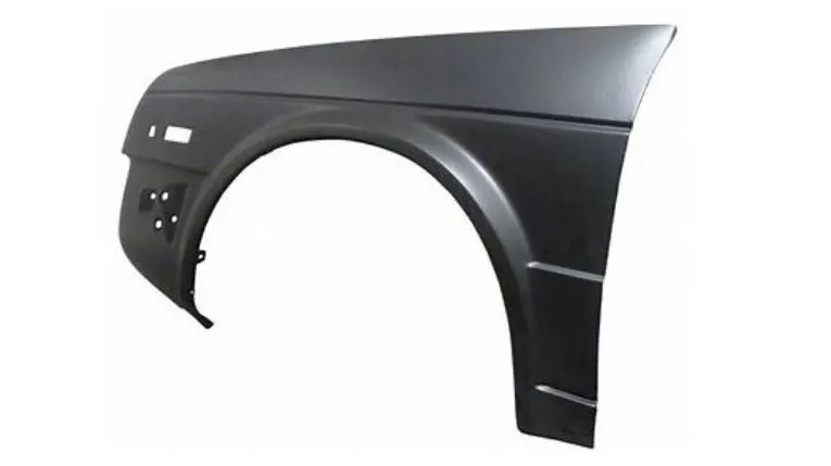
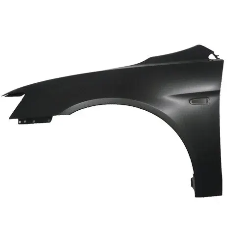
2. Half bumper type fender:
Half bumper type fender is also known as a partial fender. It is a type of fender that only covers a portion of the wheel like the upper or rear sections. It is more commonly used in nowadays due to its lighter weight and better efficiency. It also helps with better scrap management because less material is wasted when manufacturing a half bumper type fender.
Fender mounting areas:
The fender has 5 mounting regions:
- A-pillar mounting
- Baffle mounting
- Sill mounting
- Bumper mounting
- Drip mounting
Purpose of Fender:
- Fender helps to prevent debris and waste material from the road from getting into the car.
- It also prevents water, dust, snow, ice, etc. from entering the vehicle and the engine compartment.
- It provides better pedestrian safety as the impact from fender is much lesser than a direct impact from the wheel.
- It also helps with the aerodynamics of the car by preventing drag and air resistance.
Procedure for creating the mounting regions:
- Initially, the size of the flange needs to be adjusted by trimming off the excess portions. The full length of the flange is to be left only in the regions where the mounting areas will be created.
- To do this, "offset in face" tool is to be used. Select the tool and using tangent curves filter, select the edge of the flange. Offset it by 5 mm.
- Using "curve on surface" tool, create splines to mark the regions where mountings are to be created. Trim off the excess sheet metal using "trim sheet" command.
For Drip Mounting Area:
Drip area master section has been provided along with the skin data.
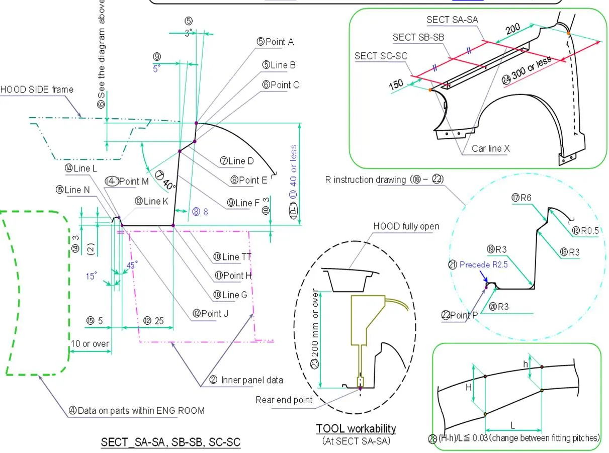
- Create datum planes to mark the region where the drip area needs to be. They need to be at a minimum distance of 150 mm from both ends of the fender edge where drip mounting is being created.
- Then create an intersection curve between the datum plane and the fender skin.
- Then create splines on the surface to mark the ends of the mounting area. Create a law extension using vector mode. Select the horizontal vector and give an angle of 40 degrees for a distance of 8mm and adjust the direction as per the master section.
- Now to create the second section, select law extension tool again and select the edge of the previous surface. Select the horizontal vector as the direction and give an angle of 85 degrees which would give us the desired 5 degree angle with the vertical.
- Adjust the length such that the distance between the top and the end of this surface does not exceed 40 mm. A value of 17 mm has been used in this project.
- Create another law extension which is horizontal this time for a distance of 25 mm.
- Now a new law extension is created that is at a 45 degree angle upwards, for a distance of 4.24 mm which is obtained through calculations made from the master section data.
- Create another horizontal law extension for a distance of 1.5 mm. Finally another law extension of angle 75 degrees and length 2 mm is to be created. This final portion needs to be greater than 5 mm.
- Provide blends as required by referring to the master section. Leave out the edge where darts need to be created.
- Create a sketch on the horizontal surface of the drip area mounting region to create the fixation points. Create provisions for embosses as well as holes. Make sure the sketch is fully constrained. The hole diameter needs to be 5 mm.
- To create embosses, project the emboss provisions from the sketch onto the surface. Then create embosses as with a depth of 3.5 mm and a draft angle of 15 degrees. Be sure to provide blends.
- Then project the holes from the sketch onto the same surface and using trim sheet command, create holes in the drip area mounting region.
- Sew this with the main fender skin. Darts can only be provided once the surfaces are sewn together.
- Now provide darts to improve the strength of the region using "dart" command.
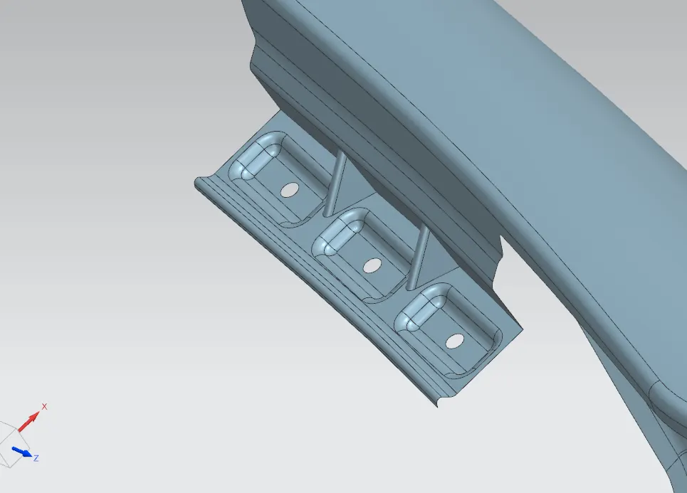
For A-pillar Mounting Area:
- At the region for the A-pillar mounting, create a law extension of required length, of about 40 mm. If there are any irregular regions of this surface, using curve on surface tool, create boundaries and trim off the excess regions.
- Create a datum plane using inferred type and offset it by about 5 mm. Create a sketch with this datum plane as the reference and construct the provisions for the hole and the emboss. Make sure the sketch is fully constrained and that fillets are created for the sharp corners. The hole diameter needs to be 5 mm.
- Project the emboss provision from the sketch onto the surface first and create emboss for a depth of 5 making sure there is enough provision for aesthetic edge blends. Also ensure a draft angle of 15 degrees is provided.
- Now project the hole and trim it off. Provide with final blends as required.
- Use bridge curve tool to create arcs on the sharp corners of the A-pillar mounting area and trim sheet with the bridge curves as the tool.
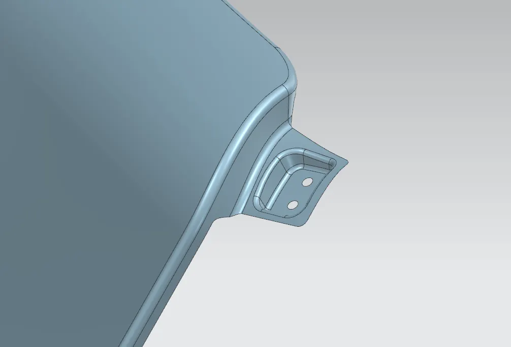
For Bumper Mounting Area:
- At the region for the bumper mounting, create a law extension of required length, of about 45 mm. A longer law extension is provided as this region needs darts to improve strength and embosses cannot come in the way.
- Create a datum plane using inferred type. Create a sketch with this datum plane as the reference and construct the provisions for the hole and the emboss. Make sure the sketch is fully constrained and that fillets are created for the sharp corners. The hole diameter needs to be 5 mm.
- Project the emboss provision from the sketch onto the surface first and create emboss for a depth of 3.5 mm and ensure a draft angle of 15 degrees is provided.
- Now project the hole and trim it off. Provide with final blends as required.
- Use bridge curve tool to create arcs on the sharp corners of the Bumper mounting area and trim sheet with the bridge curves as the tool.
- Make sure the two surfaces are sewn together before providing darts, as darts cannot be created on blended surfaces or surfaces that have not been sewn together.
- Provide as many darts as deemed necessary to improve the strength adequately.
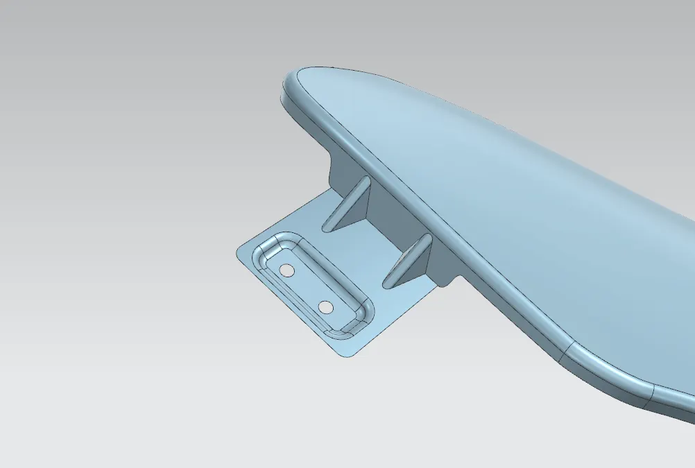
For Sill Mounting Area:
- The region for the sill mounting area is in the same direction as the flange. So instead of law extension, "Extend Sheet" tool can be used. Extend this sheet for a distance of 15 mm.
- Create a datum plane using inferred type on this extended surface. Create a sketch with this datum plane as reference and construct provisions for the emboss and the hole. The hole diameter needs to be 5 mm.
- Project the emboss provision from the sketch onto the surface first and create emboss for a depth of 3.5 mm and ensure a draft angle of 15 degrees is provided.
- Now project the hole and trim it off. Provide with final blends as required.
- Use bridge curve tool to create arcs on the sharp corners of the sill mounting area and trim sheet with the bridge curves as the tool.
- Also, using curve on surface tool, provide reliefs at the points where the sill mounting area is extended out. Use trim sheet tool again to cut necessary reliefs.
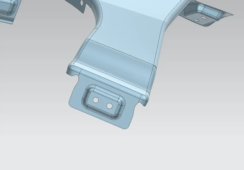
For Baffle Mounting Area:
- Fender can be mounted on the baffle easily without the need for any sort of embosses or law extensions. It can be done on the flange itself.
- Create datum planes using inferred type on each of the 3 sections of the flange. Create sketches on each of the sections taking the corresponding datum planes as reference.
- These sketches need to contain as many holes as required to mount the fender. Make sure the sketches are fully constrained and the diameter of each hole is 5 mm.
- Use project curve tool to project these holes onto the corresponding surfaces and use trim sheet tool to cut holes into the flanges.
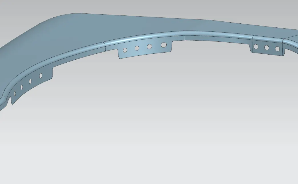
Now all that is left is thickening of the surface. Use thicken tool from surface workbench and thicken the entire fender by 0.75 mm.
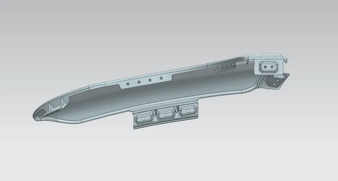
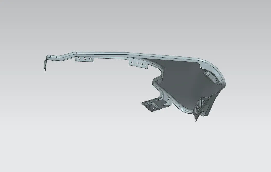
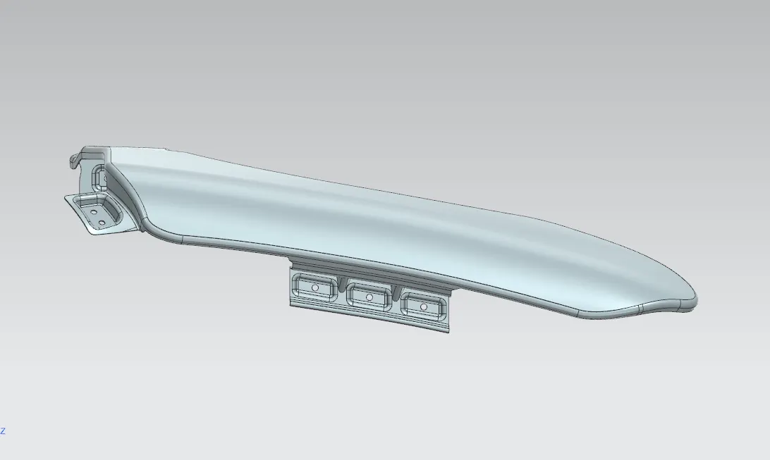
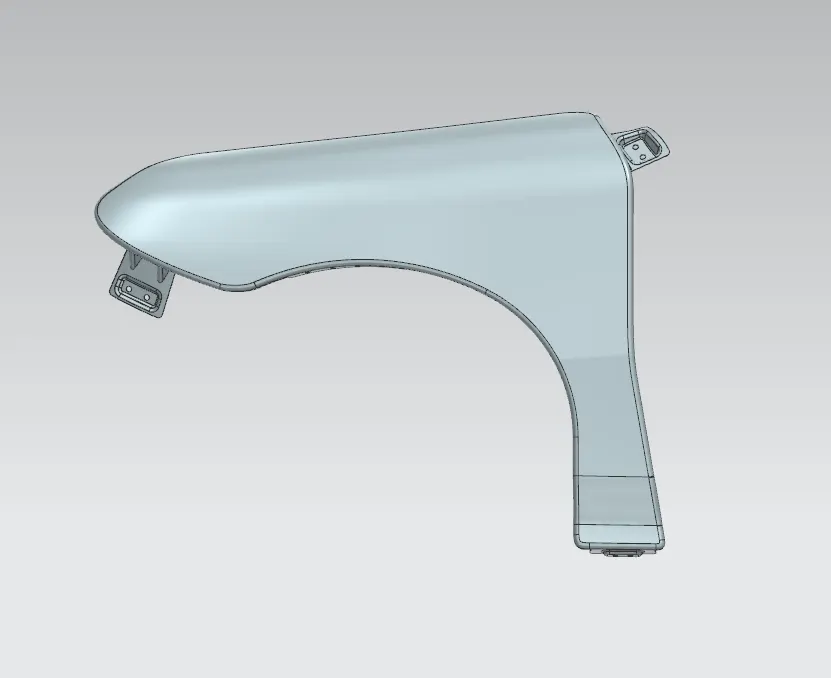
Different views of the fender:
Conclusion:
Thus all mounting areas for the fender have been created.