Fender Design
AIM:
To design the Front Fender of a car as per master section given for the drip mounting regions and as per design consideration and manufacturing feasibility using software CATIA V5.
INTRODUCTION:
Design of any product starts from an requirement . The design engineer sketches the product based on the the requirement . Then the 2D sketch with the proper dimensions is converted into the 3D model using the advanced CAD software's . The another important thing in the design is that , every product that is designed should be able to manufactured, so the role of the design engineer is to design the product that can be easily manufactured and with less cost effective . This is the place where the Design for manufacturing [DFM] and Design of assembly [DFA] takes a role while developing any product . The process of development of design carries on until the design satisfies the customer needs .Here in this project the product that we are going to develop is a car fender.
Front Fender:
Fender is the term for the part of an vehicle body that frames a wheel well (the fender underside). Its primary purpose is to prevent sand, mud, rocks, liquids, and other road spray from being thrown into the air by the rotating tire. Fenders are typically rigid and can be damaged by contact with the road surface.Sticky materials, such as mud, may adhere to the smooth outer tire surface, while smooth loose objects, such as stones, can become temporarily embedded in the tread grooves as the tire rolls over the ground. These materials can be ejected from the surface of the tire at high velocity as the tire imparts kinetic energy to the attached objects. For a vehicle moving forward, the top of the tire is rotating upward and forward, and can throw objects into the air at other vehicles or pedestrians in front of the vehicle.
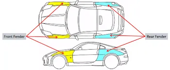
Types of Fender in Vehicles:
- Full bumper type Fender
- Half bumper type Fender
Different mounting regions in a Fender:
- Drip Area for Hood: It is the critical mounting area located near the engine compartment over which hood is mounted and both this component screwed together to arest some degrees of freedom for fender and to maintain a optimal opening angle for the hood is being design as per design consideration.
- A-pillar area : It is located at the top corner of the fender to mount A Pillar.
- Drip area for Bumper: It is located just below the headlight area to mount the front bumper and to arest some degrees of freedom for both the component.
- Drip area for Sill: It is located at the bottom (foot rest area known as sill area over this region the sill is mounted with the help of fastners.
- Drip area for Baffle: Ist is located over the wheel arc the purpose of designing this is to prevent sand,mud, rocks,liquids and another road spray from being thrown into the air by the rotating tire.
Input skin given
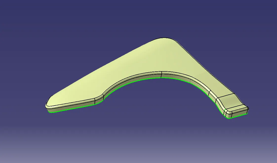
From the above input skin surface it is observed that there is discontinouties in some areas, so we do need modify the input skin and fixed those dicontineuties by extrapolating and trimming the egde of surface
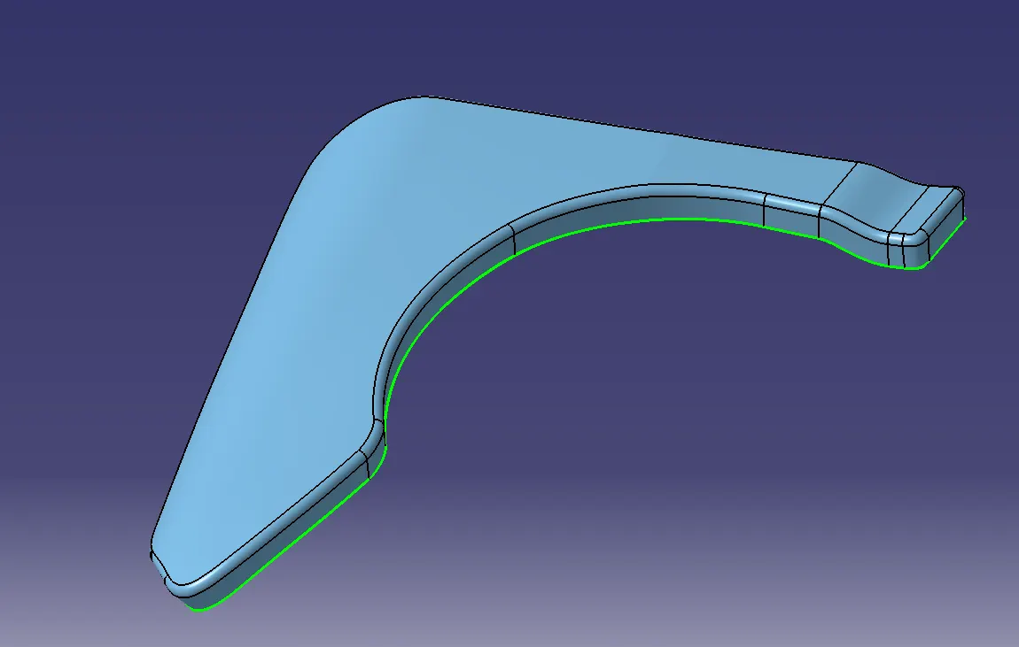
It can seen that in the above image there is no open boundaries hence we can proceed with over design.
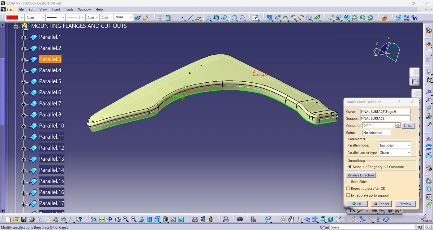
We have offseted to a distance of 5 mm to have a minimum distance for flange over which drip area is mounted
'Parallel curve' command is used to offset the curve from egde of the surface.
Drip area for Hood mount region

Drip area for front bumper mount region
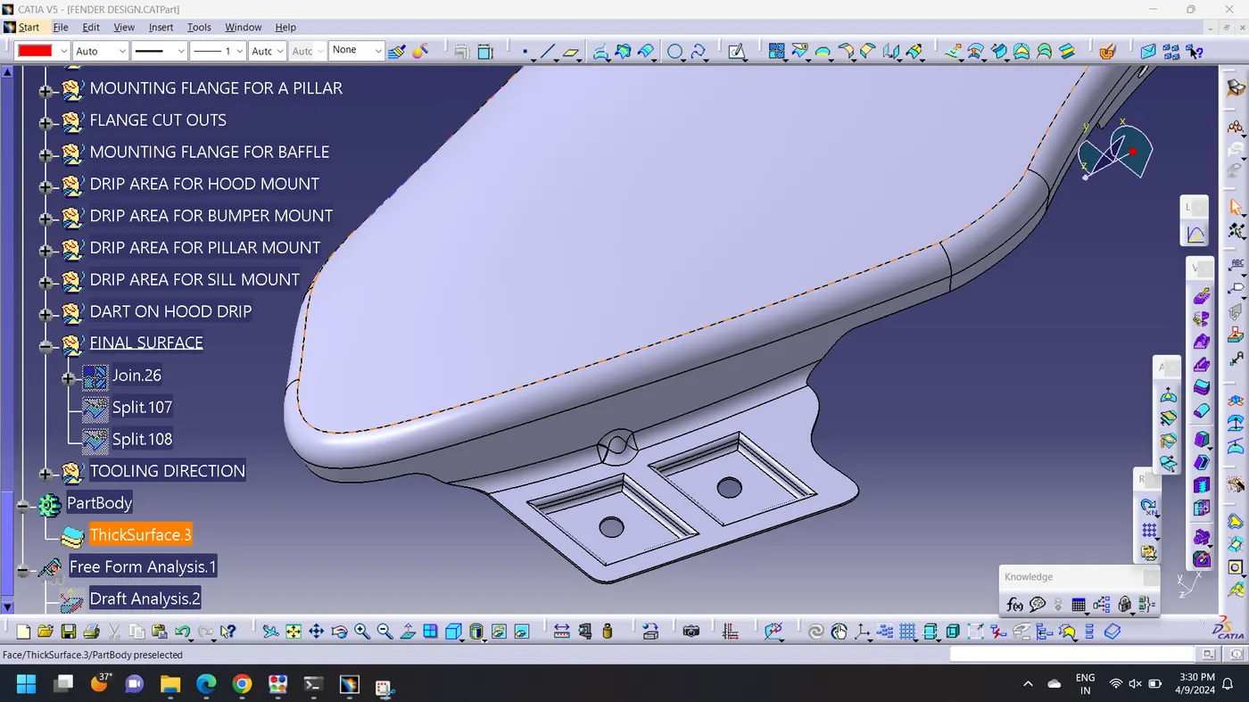
A Pillar Mounting region
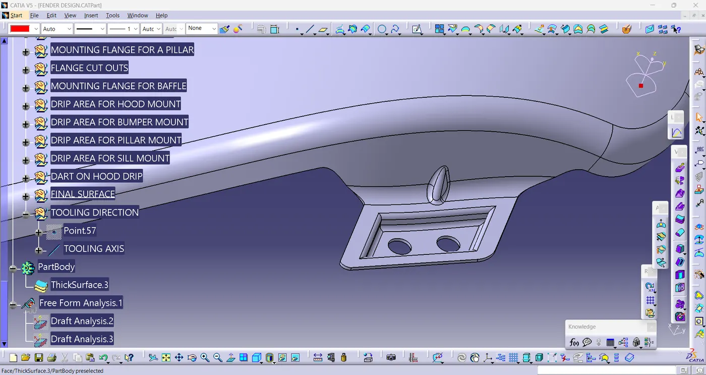
Sill Mounting region
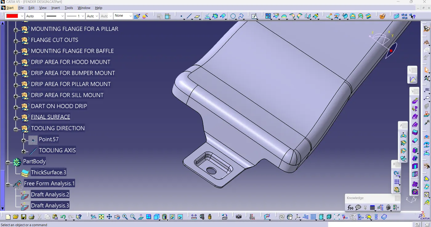
Baffle Mounting region
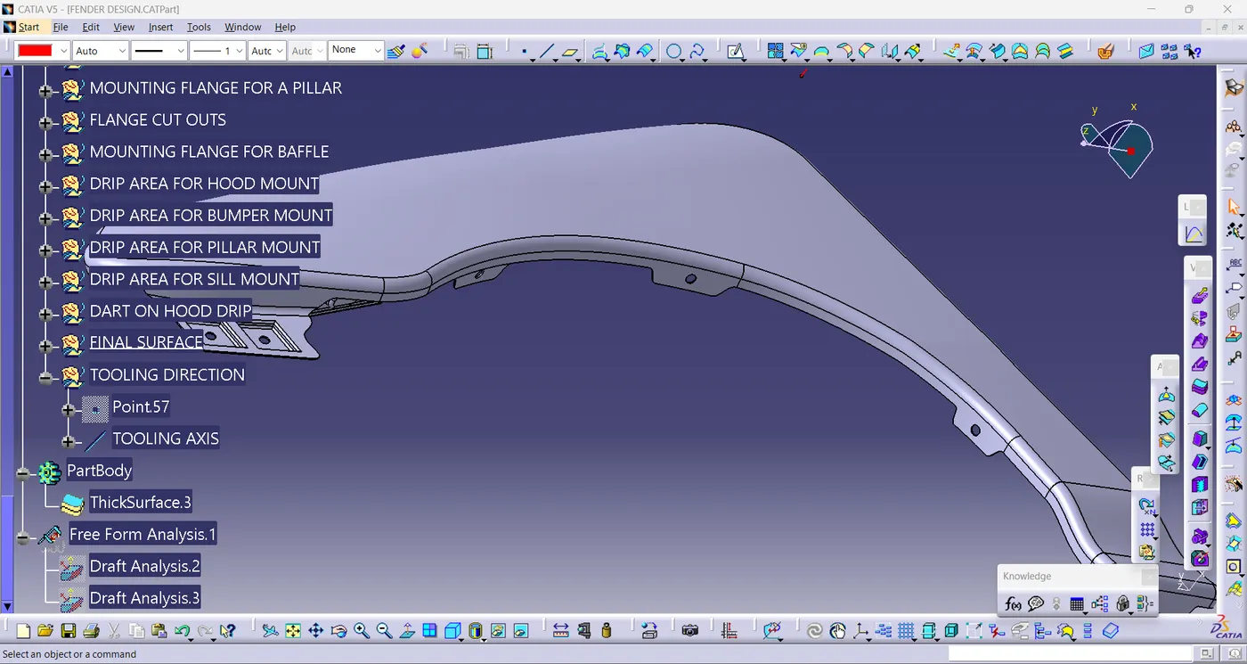
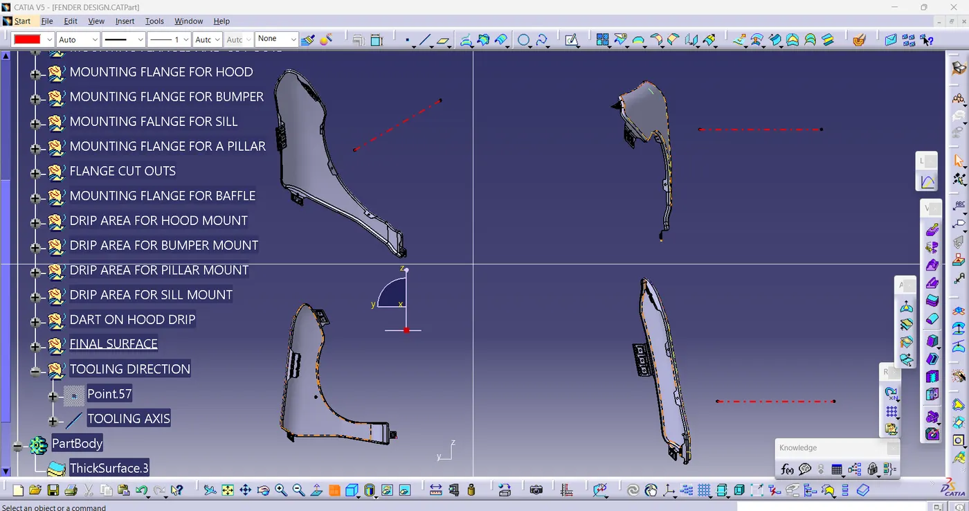
Final component
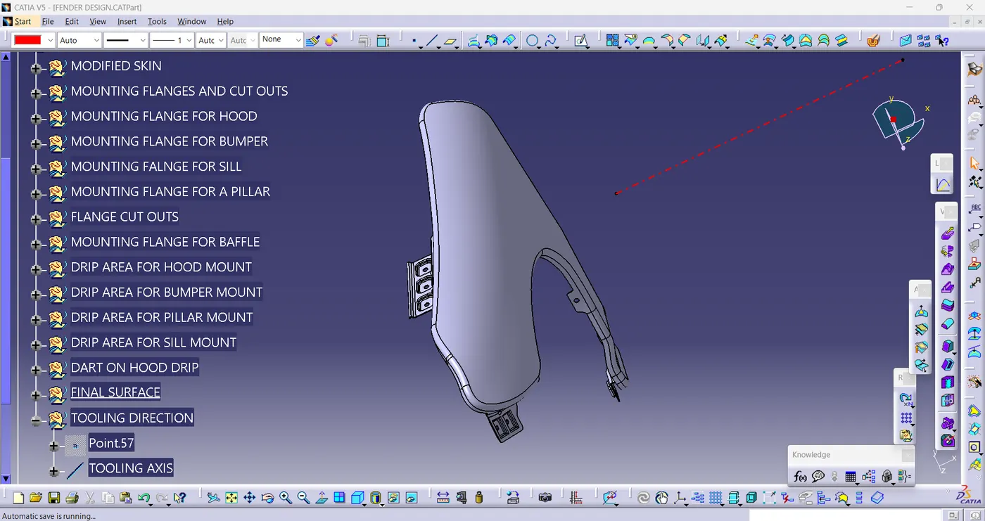
Different orientation views
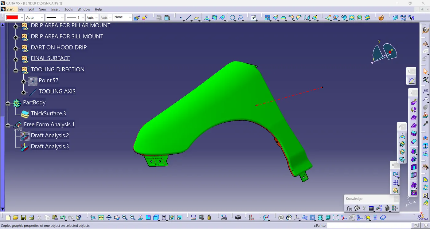
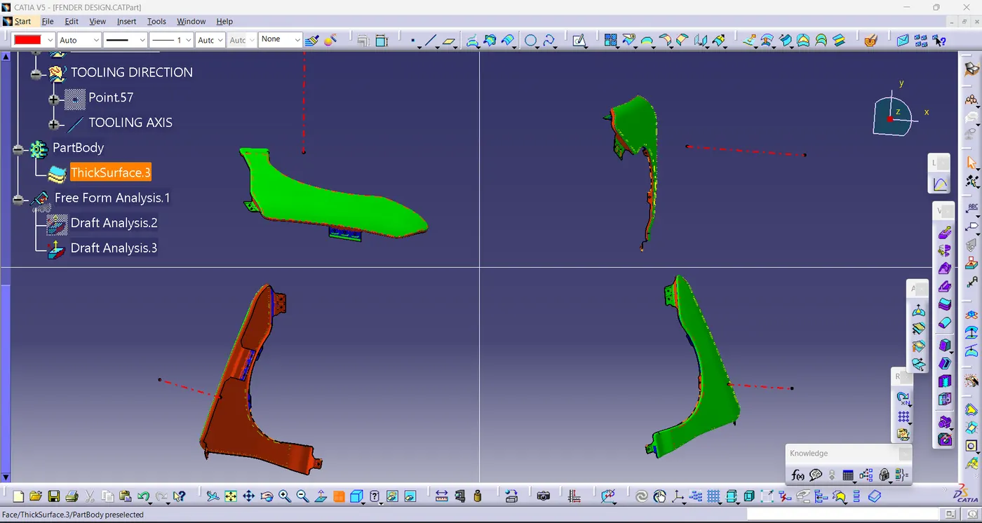
Tooling feasibility in a draft analysis
Conclusion:
Thus as per design conisderation and following the master section succefully designed the 'Front Fender'.