Fender Design
Fender Design
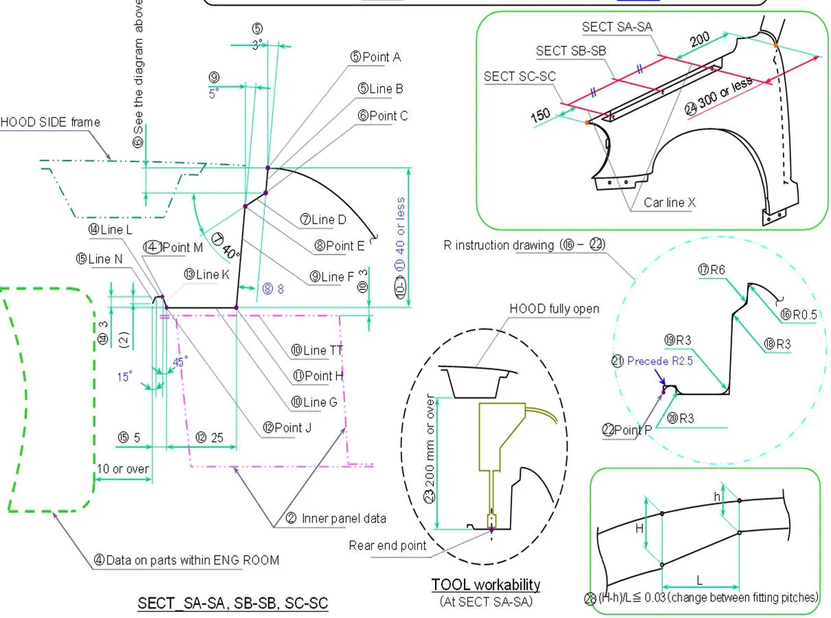
AIM = Follow the given Master section to create the Drip Area. Create design according to the Engineering standard for the Sill, Bumper, Baffle(Splash), and A-Pillar mount with a report with all the relevant images included for the mounting points created.
DESCRIPTION
- Fender - Aesthetic component widely seen in cars that frames the body near to the wheel frame, manufactured with plastic, metal or rubber panel which extends from front bumper to car door.
-
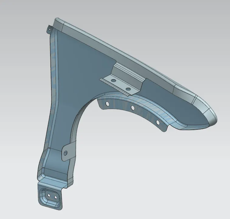
There are 5 mounting regions on the fender , they are
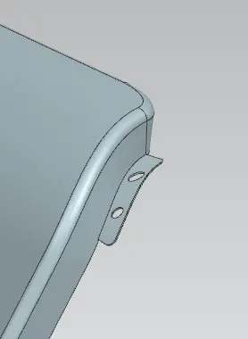
- A- pillar mounting - Designed to attach the fender to A Pillar of the vehicle.
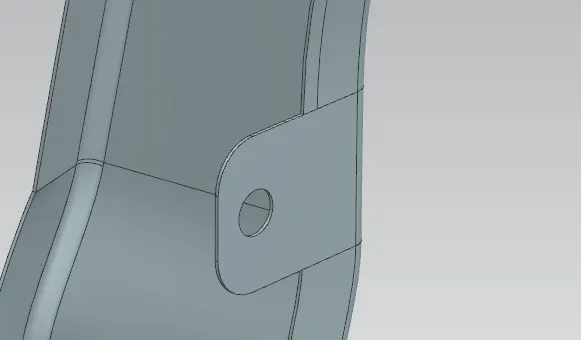
- Baffle mounting - Created for attaching plastic components i.e baffle which prevents chipping inside the engine compartment.
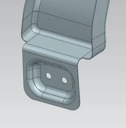
- Sill mounting - Created on the bottom portion of the fender for attaching to the sill.
- Drip mounting - The point where the fender has to be attached to the engine compartment.
- The drip area should be designed in such a way that it should be at least 150mm away from the front end of the fender to have sufficient space for mounting headlamps housing.
- Mostly the drip area starts from 200mm away from the rear end of the fender, to have sufficient space for the cowl which carries the wiper equipment
-
Purpose of Fender :
- Protects car's internal frame from water, mud, snow, ice, thrown off the tires as you drive.
- Provide safety, good aerodynamics and better surface finish to make a close component.
SOFTWARE USED
- NX
REPORT
- As the inputs of master section, class A and dimensions are given in detail.
- Process started with creation of Sill mount followed by Baffle, A-pillar, and Drip mounts.
- The steps used in designing is properly aligned as separate feature groups in the below attatcted file.
- These mounts all are used in fender to connect the fender with other parts of car to maintain perosnal, vechicular safety, proper crash clearance and Noise vibration control tests, etc.
- Extend, sketch, project curve, trim sheet are commonly used in designing mounts for this fender. Finally it is deemed to thickening process inorder to make it a solid component.
- Detailed images and part file are attatched below for further reference.
IMAGES
- INPUT
- SILL MOUNTING AREA
- BAFFLE MOUNTING AREA
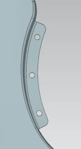
- DRIP MOUNTING AREA
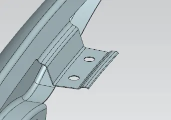
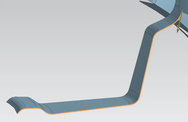
- A-PILLAR MOUNT
- FINAL PRODUCT
Note:
- Proper designing procedures as per video are provided.
- 0.75mm is the provided thickness to component.
- Fillets are provided of 3mm + thichness of the component format except those ones mentioned for drip area in the question itself.
- Tree structure are maintained properly.