Fender Design
Objective:
The main objective of this challenge is to create the mountings for the fender design by using the given A_surface.
FENDER DESIGN:
A car tire fender is a plastic, metal, or rubber panel that bends over the wheel on the side of the car, extending from the front bumper to the car door. The main function of car fenders is to protect tires and braking systems from mud or other impurities so that they are safer and more efficient.
Sticky materials, such as mud, may adhere to the smooth outer tire surface, while smooth loose objects, such as stones, can become temporarily embedded in the tread grooves as the tire rolls over the ground. These materials can be ejected from the surface of the tire at high velocity as the tire imparts kinetic energy to the attached objects. For a vehicle moving forward, the top of the tire is rotating upward and forward, and can throw objects into the air at other vehicles or pedestrians in front of the vehicle.
TYPES OF FENDER
- Full Bumper type
- Half Bumper type
Class_A_Surface:
The given fender A surface is given for to design the mountings on it,
Data given for Designing Fender in DRIP AREA:
MANUFACTURING OF FRONT FENDER :
- Process planning: The purpose of process planning of automotive panels is to identify the number of operations, the tasks in each operation, and the content of each task. This research proposes an automatic reasoning procedure based on expert experience and the laws of physics.
- Blank size calculation.
- Trimming task: The trimming task is separated into two parts.
- Restriking task: The restriking task is necessary when surfaces deform because of springback after drawing and trimming, or the accuracy requirement is high because a surface overlaps another surface of another panel during assembly. To overcome the springback of sheet metal restriking is required.
- Piercing task: Each hole feature requires a piercing task. Hole features can be classified as basic holes, lock holes, and enlarge holes based on their different functions during assembly. A basic hole is for locating the panel, and a lock hole is for locking panels.
- Burying task: Removing the sharp edges and harmful burs from the component.
Create the Drip Area:
- While designing the drip area, a 150mm clearance is maintained from the front-end for headlight fittings and 200mm clearance from the rear-end for the wiper motor assembly (Cowl top area)
- The depth of the drip area is maintained at less than 60mm so as to avoid the spring-back effect.
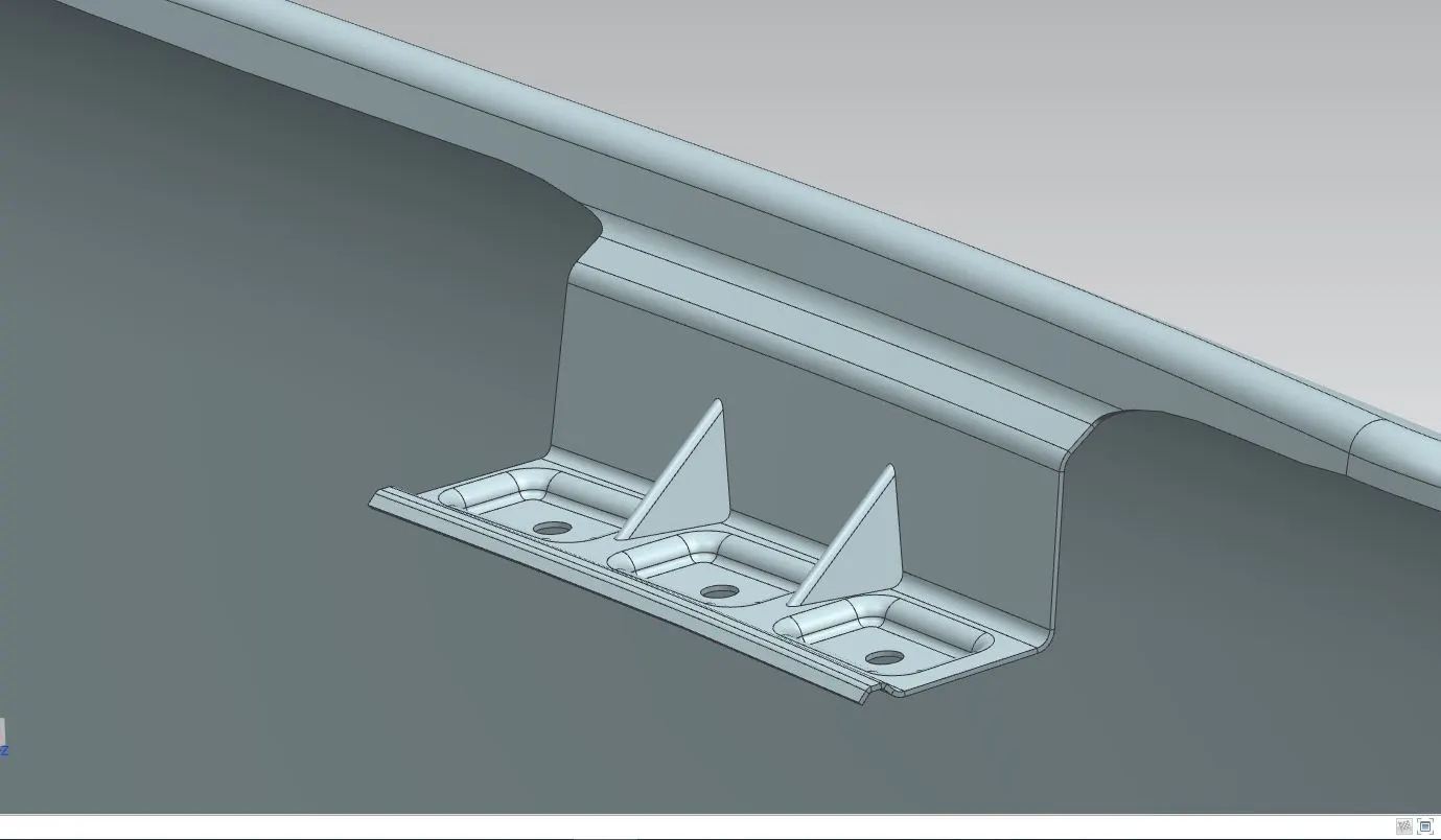
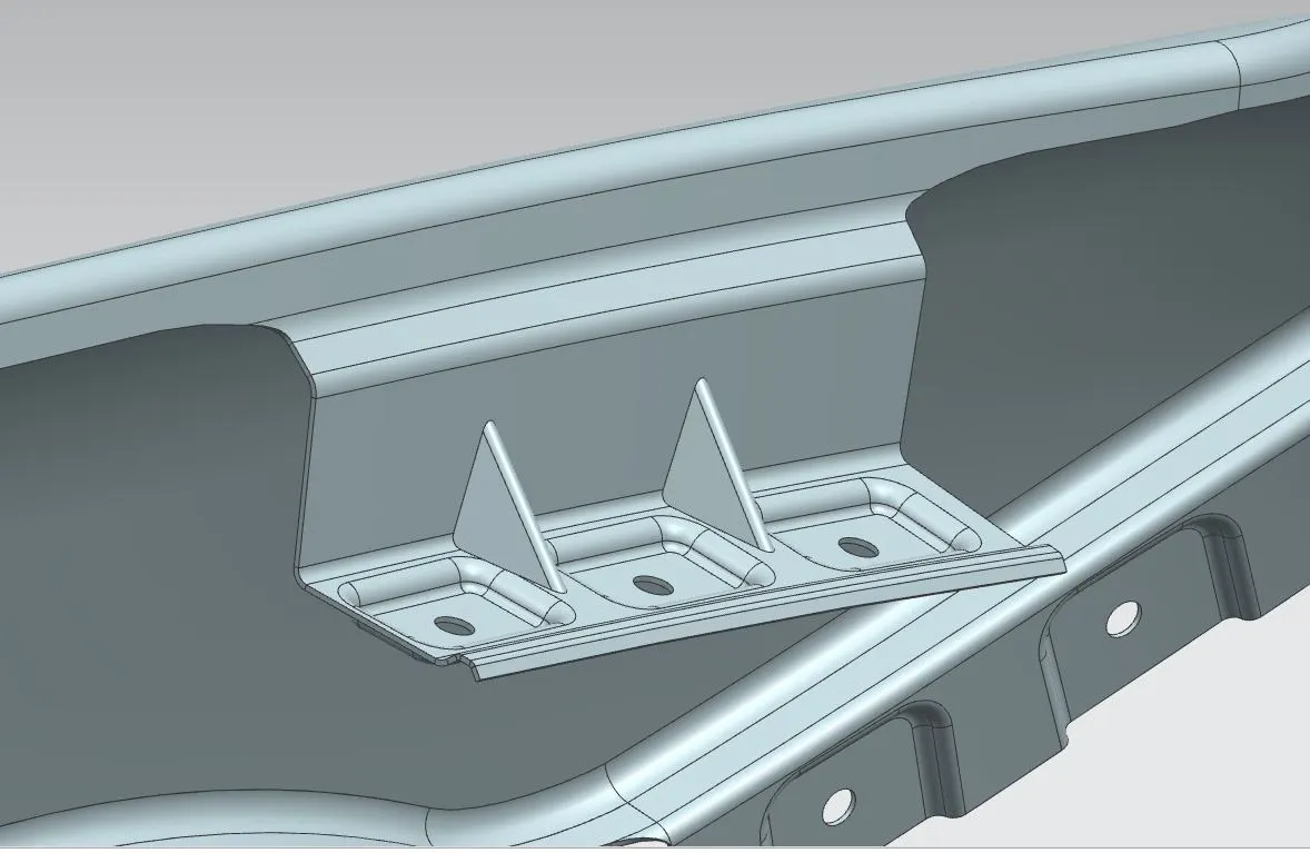
- Ribs are provided at the fender drip area to increase strength in that area.
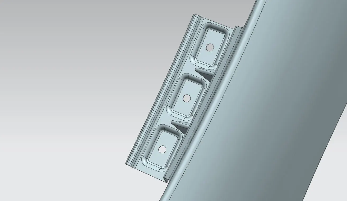
Use law extension from the given flanges of the fender following the master section. Give face blends to all the law extended flanges. Sketch the mounting area face and holes of 5 mm dia, holes should have 10mm dia flat surface. Project the sketch on the drip area surface. Create a datum plane to give emboss to that respect. Give emboss of 3mm with angle of 8 deg. Trim sheet for holes. Give face blends to emboss. Create Dart in the middle of two emboss. Give edge fillet and make sure there are no any sharp edges and should have smooth transition of surfaces.
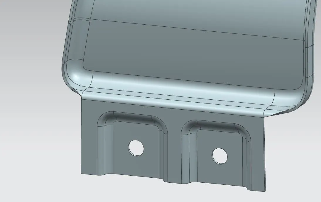
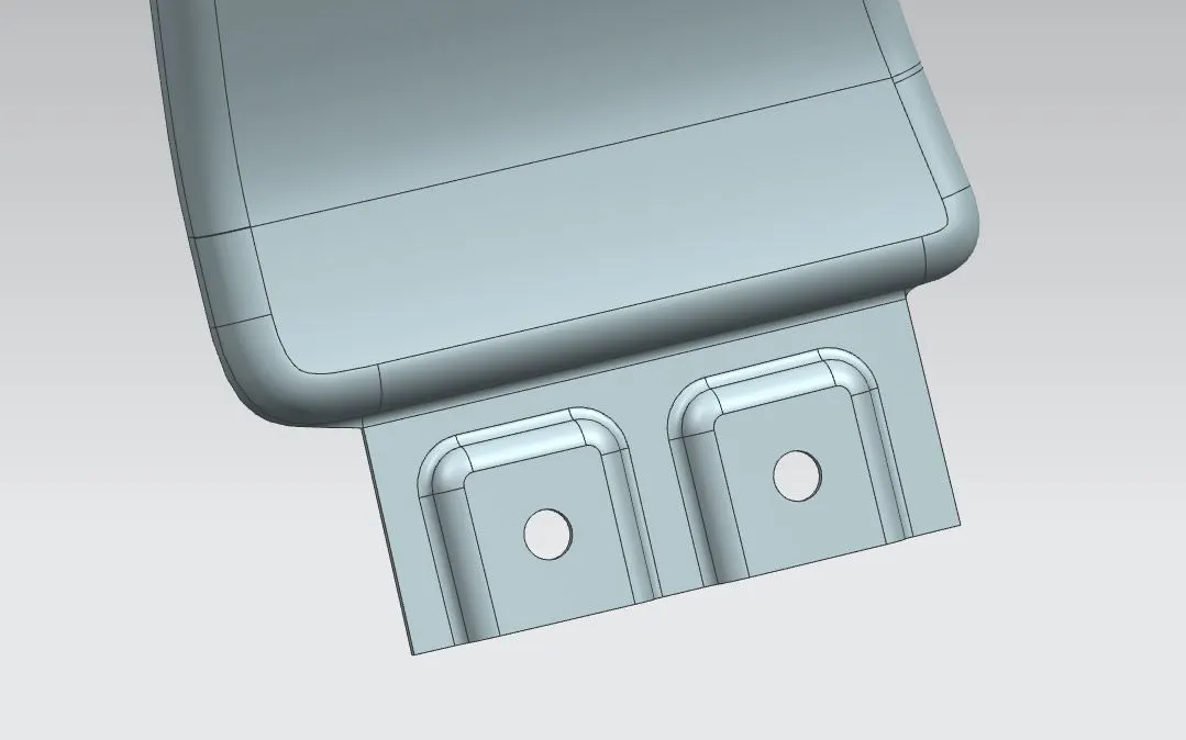
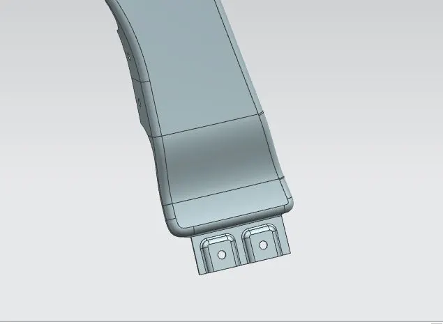
PROCEDURE TO CREATE SILL AREA MOUNTING
Extend the sheet of the fender from its edge of the sill area. And then create the law extension for 90 deg. Sketch the mounting area face and holes of 5 mm dia, holes should have 10mm dia flat surface. Give an emboss of 3mm with 8 deg angle. Give edge blends to emboss. Trim sheet for holes.
PROCEDURE TO CREATE BUMPER AREA MOUNTING
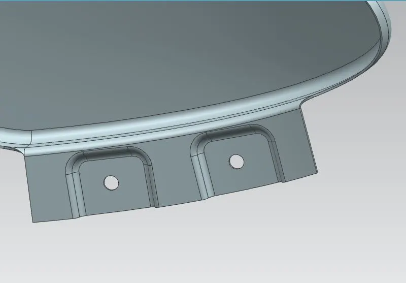
Use law extension to the 90 degrees of the face and 25 mm length. Bridge the curve to the both corners of the extended sheet. Trim the sheet to avoid sharp corner. Give an edge blend of 2.5mm. Sketch the mounting area face and holes of 5 mm dia, holes should have 10mm dia flat surface. Give an emboss of 3mm with an angle of 8 deg. Trim sheet for holes. Give edge blends to emboss making sure that there are no any sharp edges and should have smooth transition of surfaces.
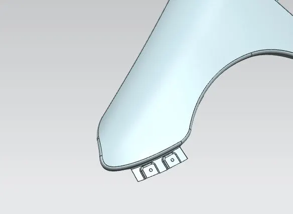
PROCEDURE TO CREATE A PILLAR AREA MOUNTING
Bridge the curve to the both corners of the extended sheet. Trim the sheet to avoid sharp corners. Sketch the mounting area face and holes of 5 mm dia, holes should have 10mm dia flat surface. Project the sketch on the A pillar area surface. Give an emboss with an end cap as the plane we created earlier. Trim sheet for holes. Give edge blends to emboss making sure that there are no any sharp edges and should have smooth transition of surfaces.
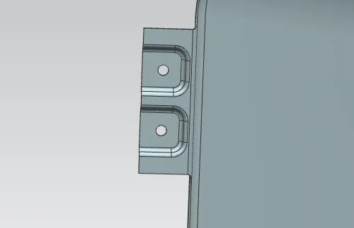
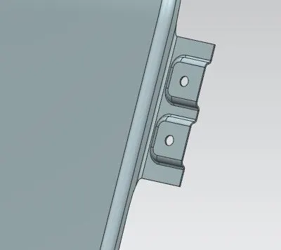
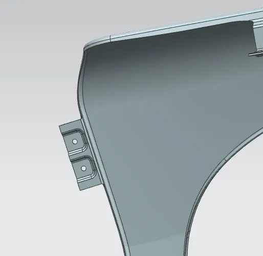
PROCEDURE TO CREATE SPLASH / BAFFLE AREA MOUNTING
Cowl Mounting Area
In this cowl mounting area we just extend the sheet and then make the embosses or holes for the mountings. Sketch the two circles of 5mm dia, holes should have a 10mm dia flat surface and have a large distance between them. Project the sketch to the surface. For this area we don't need any embosses there, it will depend upon the designing team. Trim the sheet to show the holes on the baffle area.
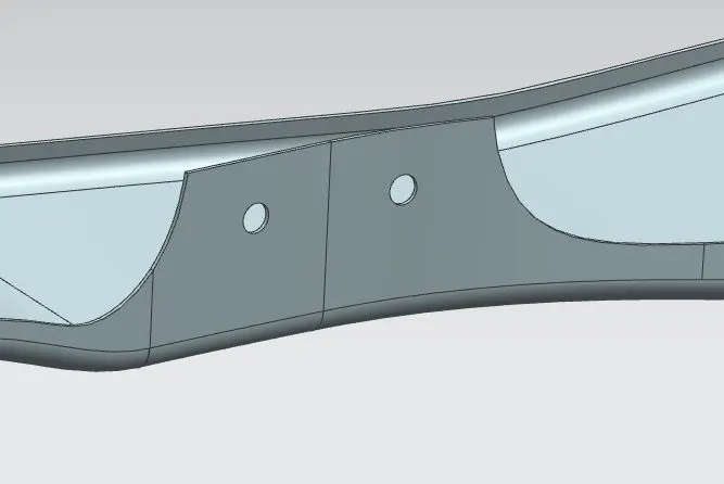
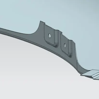
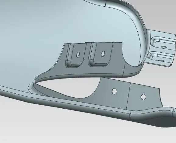
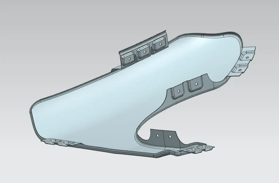
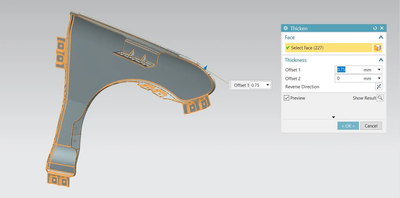
Thicken the Part :
By using the thicken tool we can thicken this sheet metal and make it as a solid profile. Here I'm giving 0.75 mm for the thickness value.