Fender Design
FRONT FENDER DESIGN
we get the class A of front fender and master sections to create the front fender
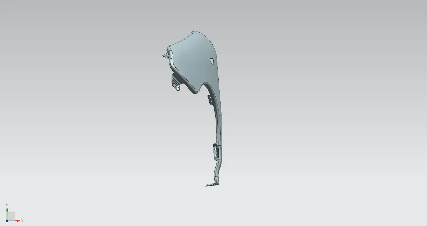
CLASS A
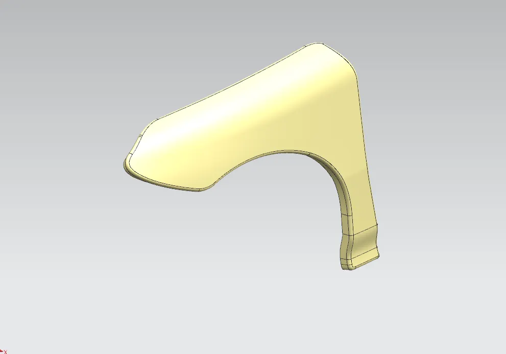
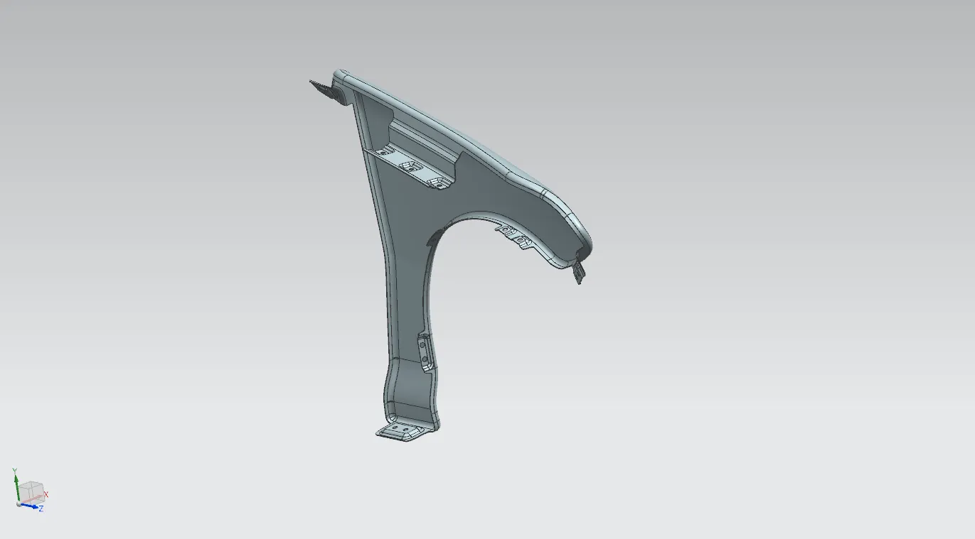
the mounding points that we have decided to create on the fender are
- Drip area mounding
- bumber area mounding
- baffle mounding points
- sill area mounding
- A piller mounding
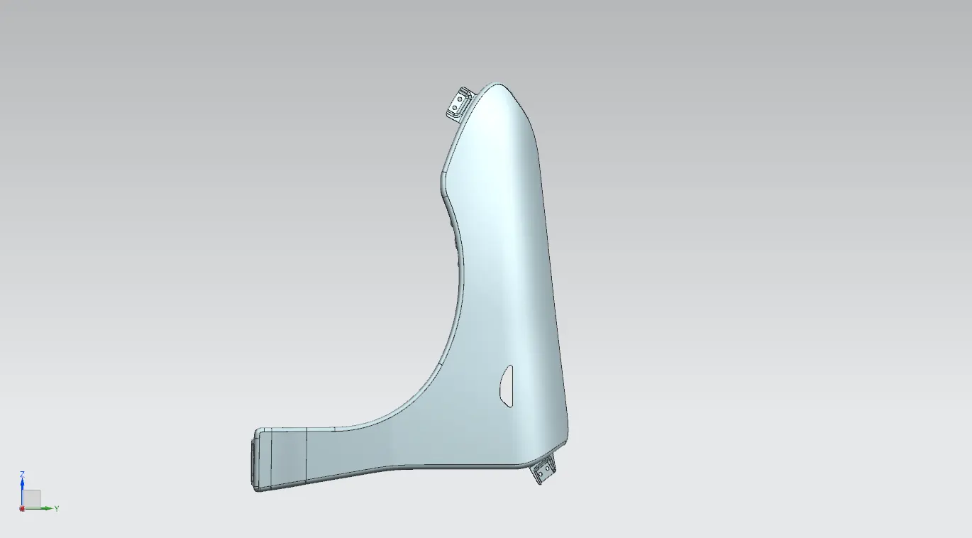
- side indicator lamp mounding point
Drip Area Mounding
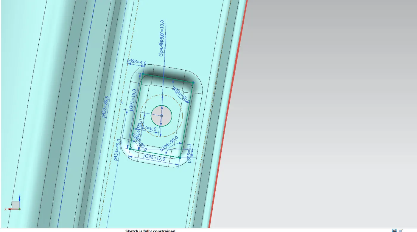
as per the master section the drip area mounding we should give a minimum of 150 mm from the front end of the fender and the rear end of the fender foe easy of head lamp mounding and cowle top mounding. foe that we offset 2 planes from each side 150mm.
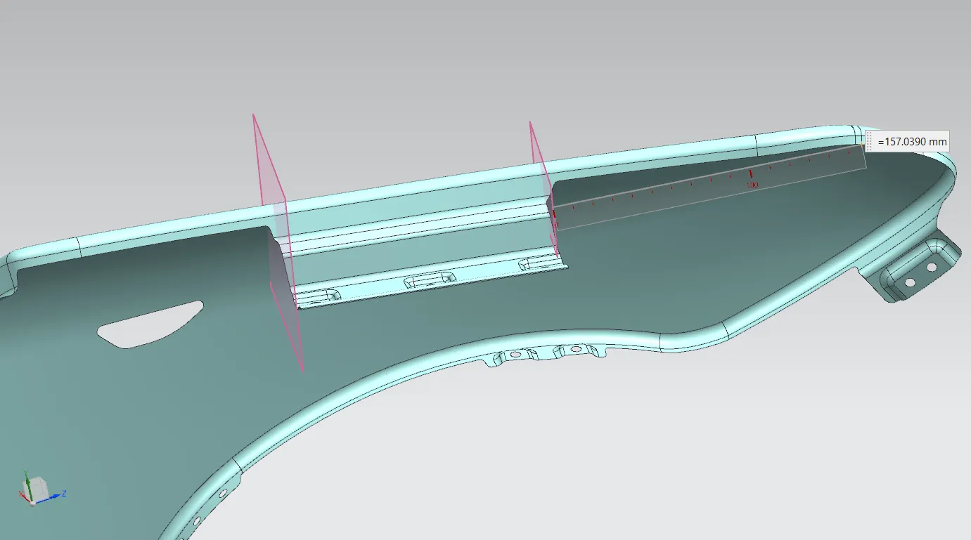
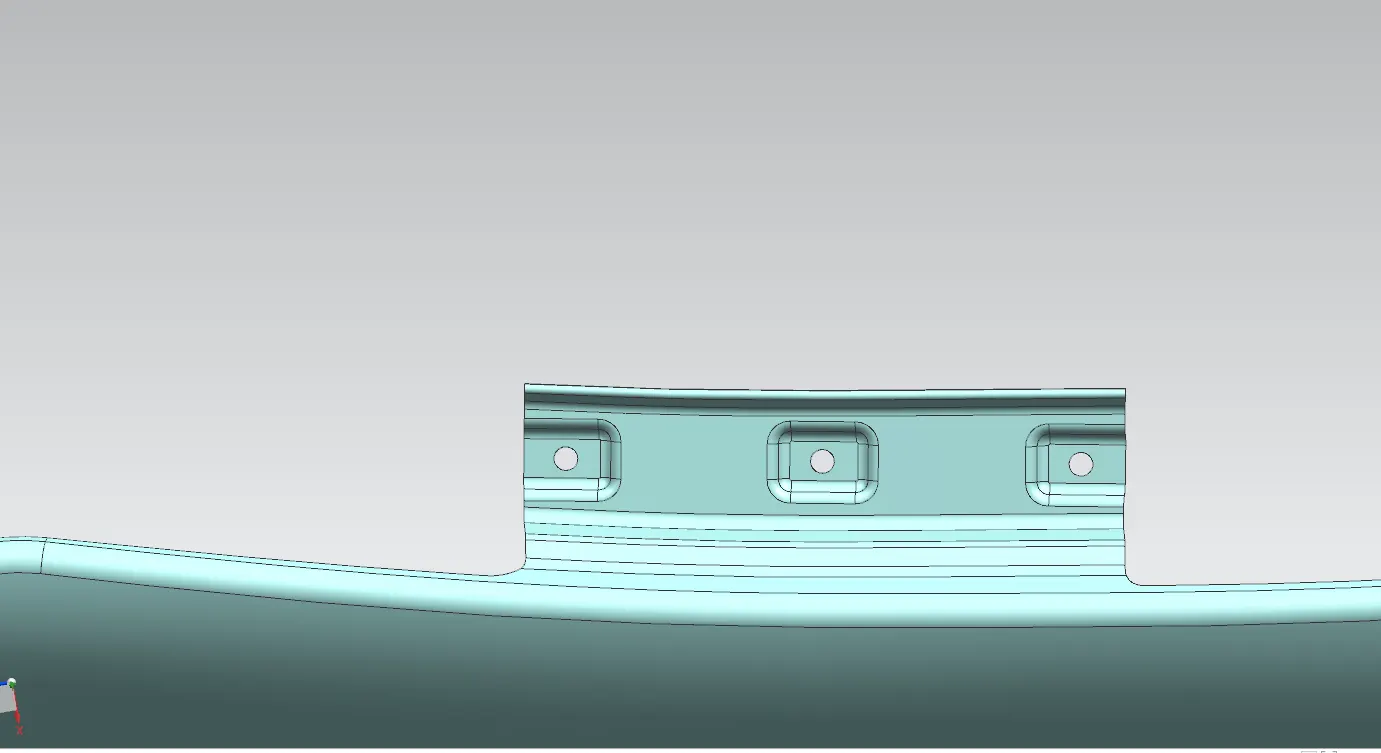
and created the flanges by following the geometrical requirments demanted by the master sections. and give 3 mounding points with embosses with 5mm dia hole.
BUMBER AREA MOUNDING
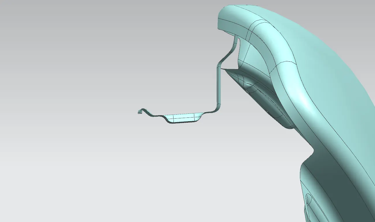
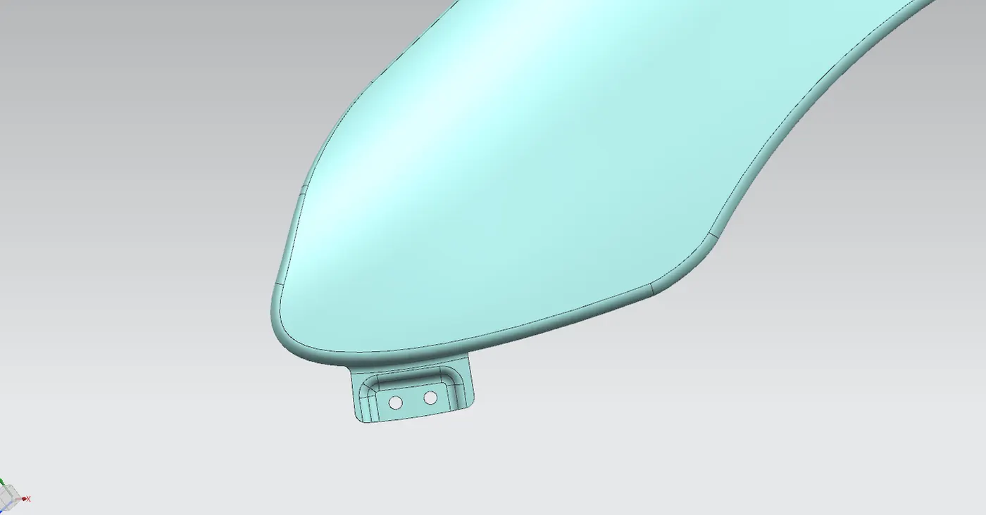
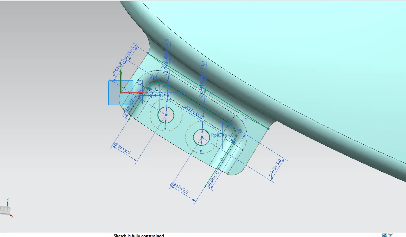
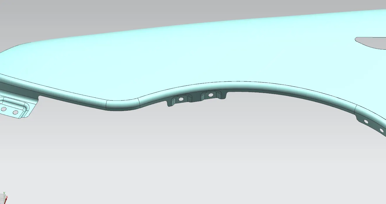
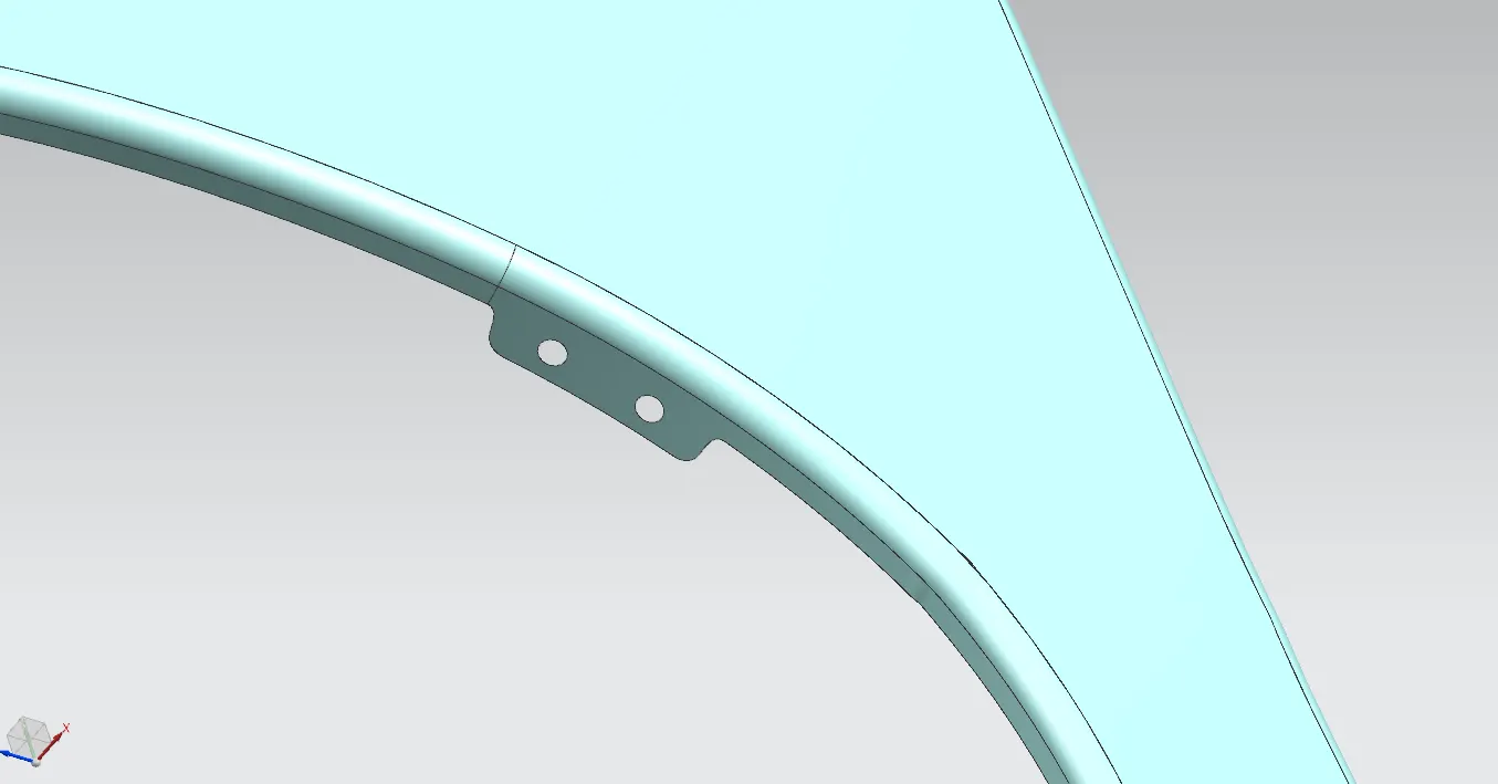
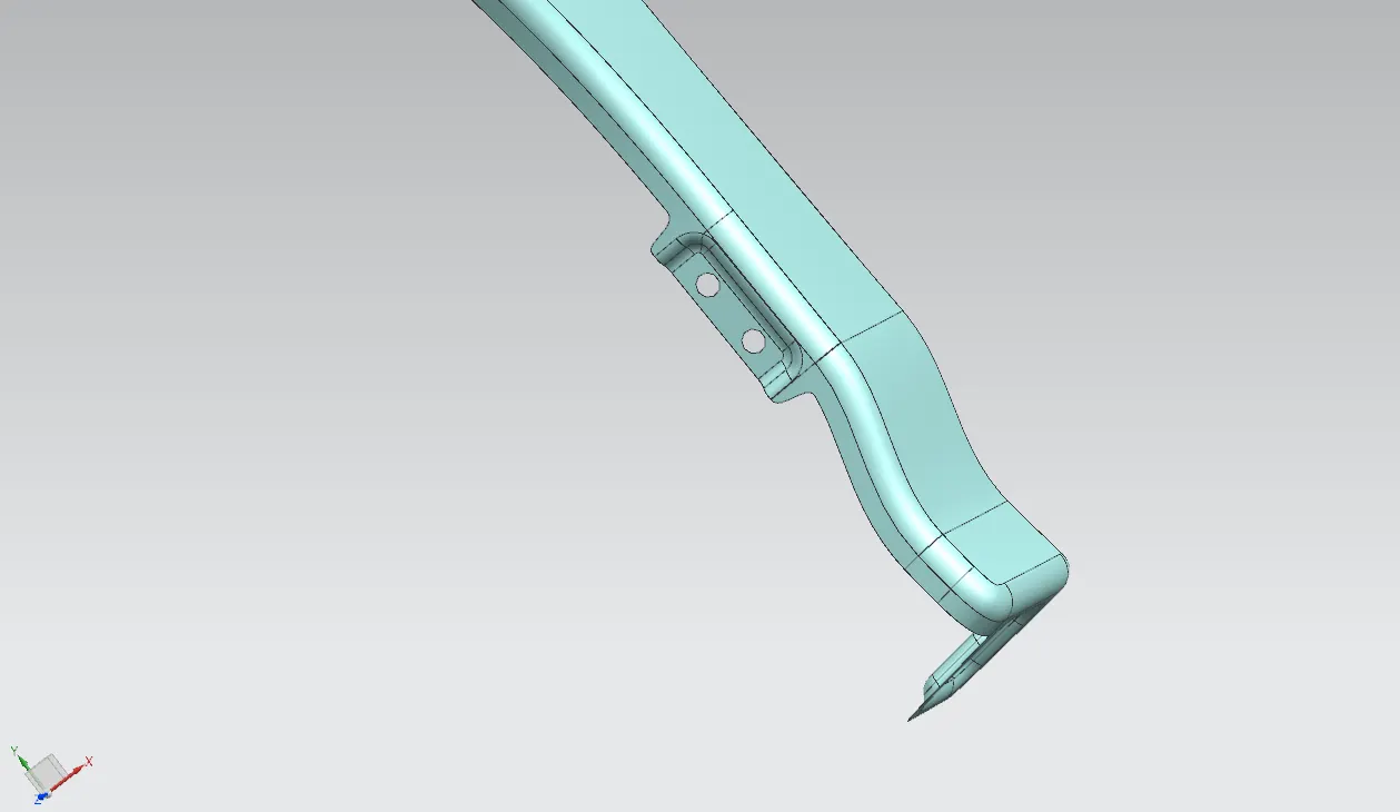
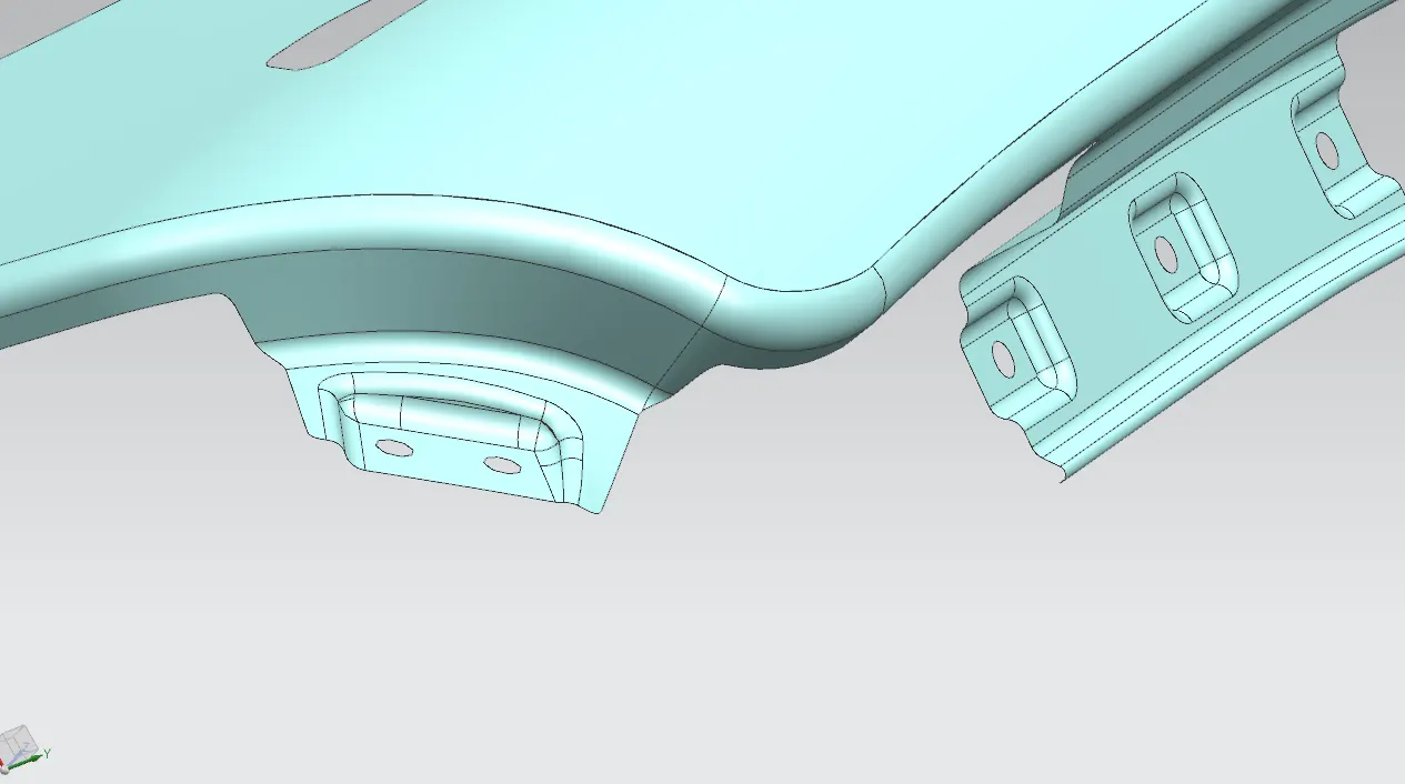
for bumber area mounding we have cutout a flange from the given class A and create a law extension. and give 2 mounding points on the law extension on a single emboss.
insted of creating a closed embosse i created a emboss with one side open and also i give 2 mounding points in one single emboss insted of 2, by this we can reduce the weight of the material and can also make the machining process easy.
BAFFLE MOUNDING POINTS
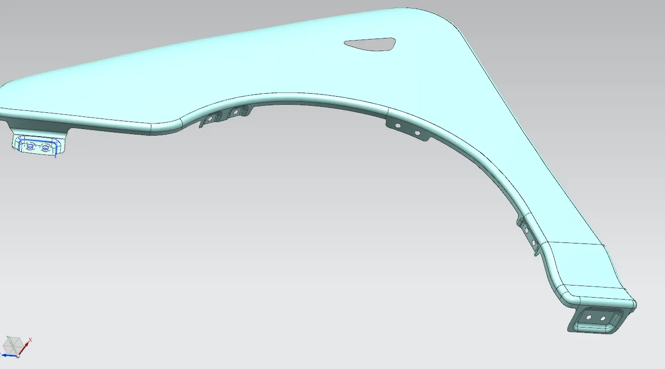
for mounding baffle we use screw and retainer clips and push clips etc. so i have created 3 mounding areas for baffles. which 2 mounding areas for using screw and one for retainer clips. so for retaier we dont have to give emboss flat surface are good for retainer joints. and the other 2 areas where we use screws for mounding baffle there we can give emboss.
SILL AREA MOUNDING
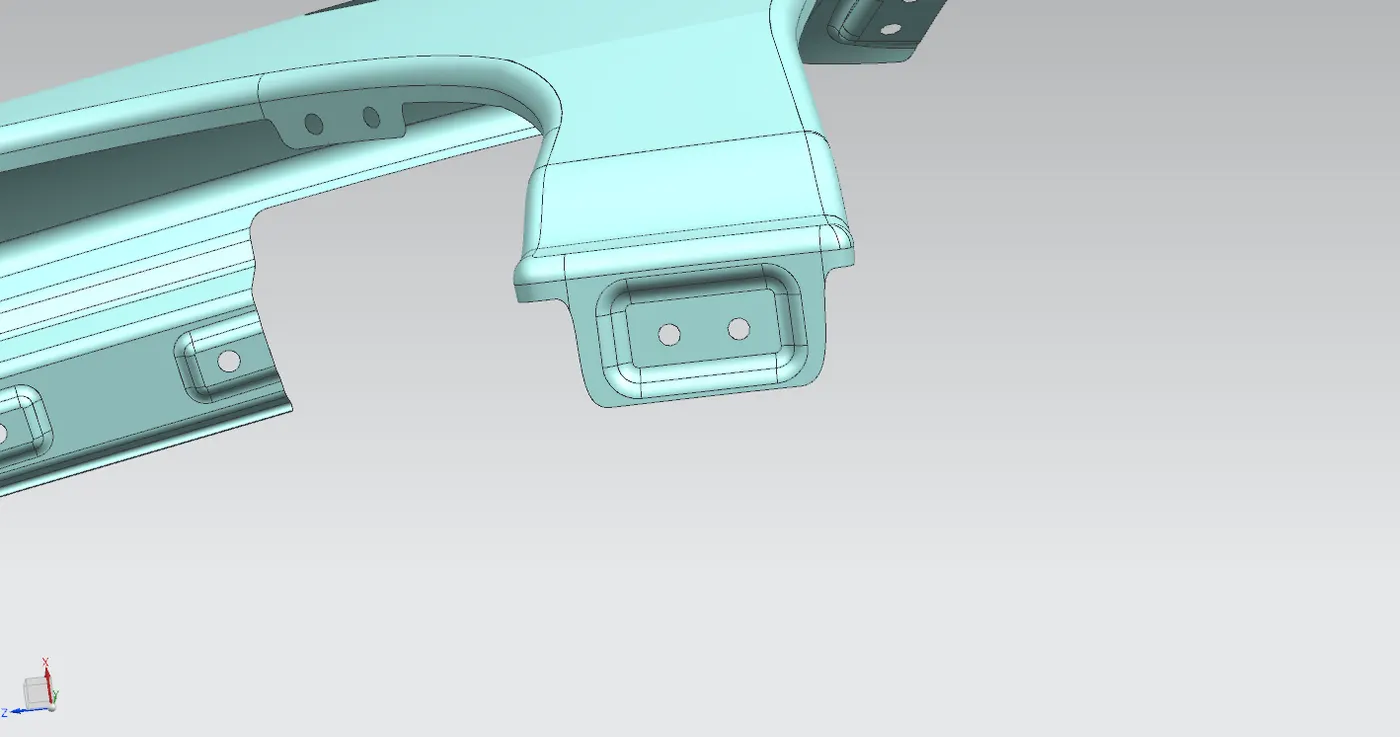
sill area mounding is not a complicated area, so we extented the sill ares of the given class A and give 2 mounding points on a single emboss which is facing the sill area of the vechicle.
A PILLER MOUNDING
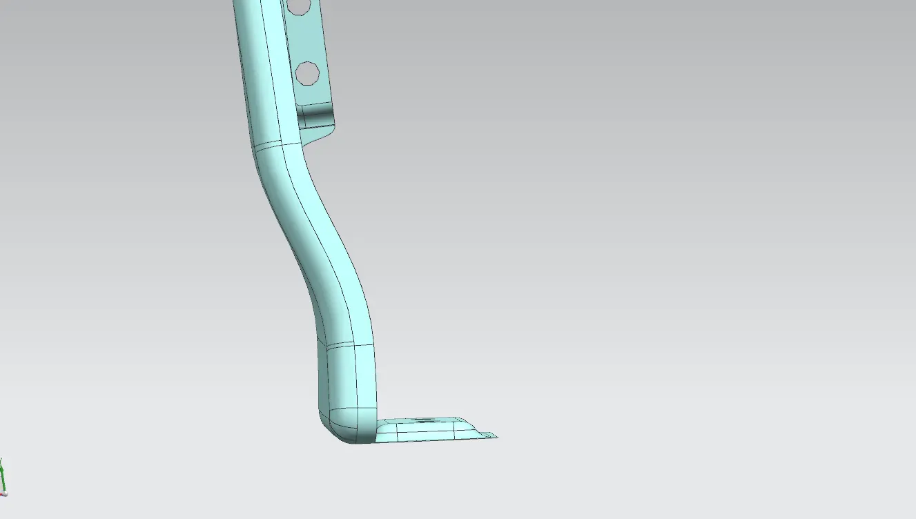
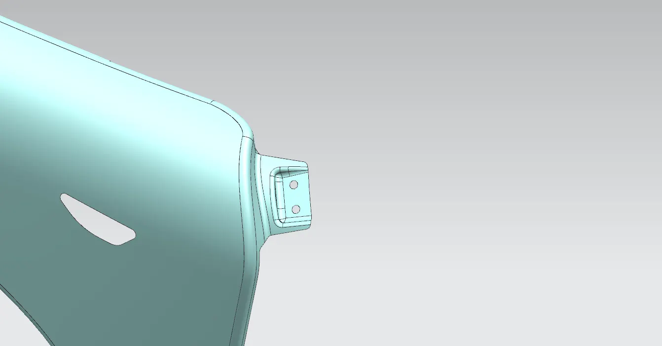
foe A piller mounding we cut a required flange from the calss A by using curve on surface and created a law extension. then give 2 mounding points on a emboss which is one side open as we mentioned before.
EMBOSS'S CREATIONS
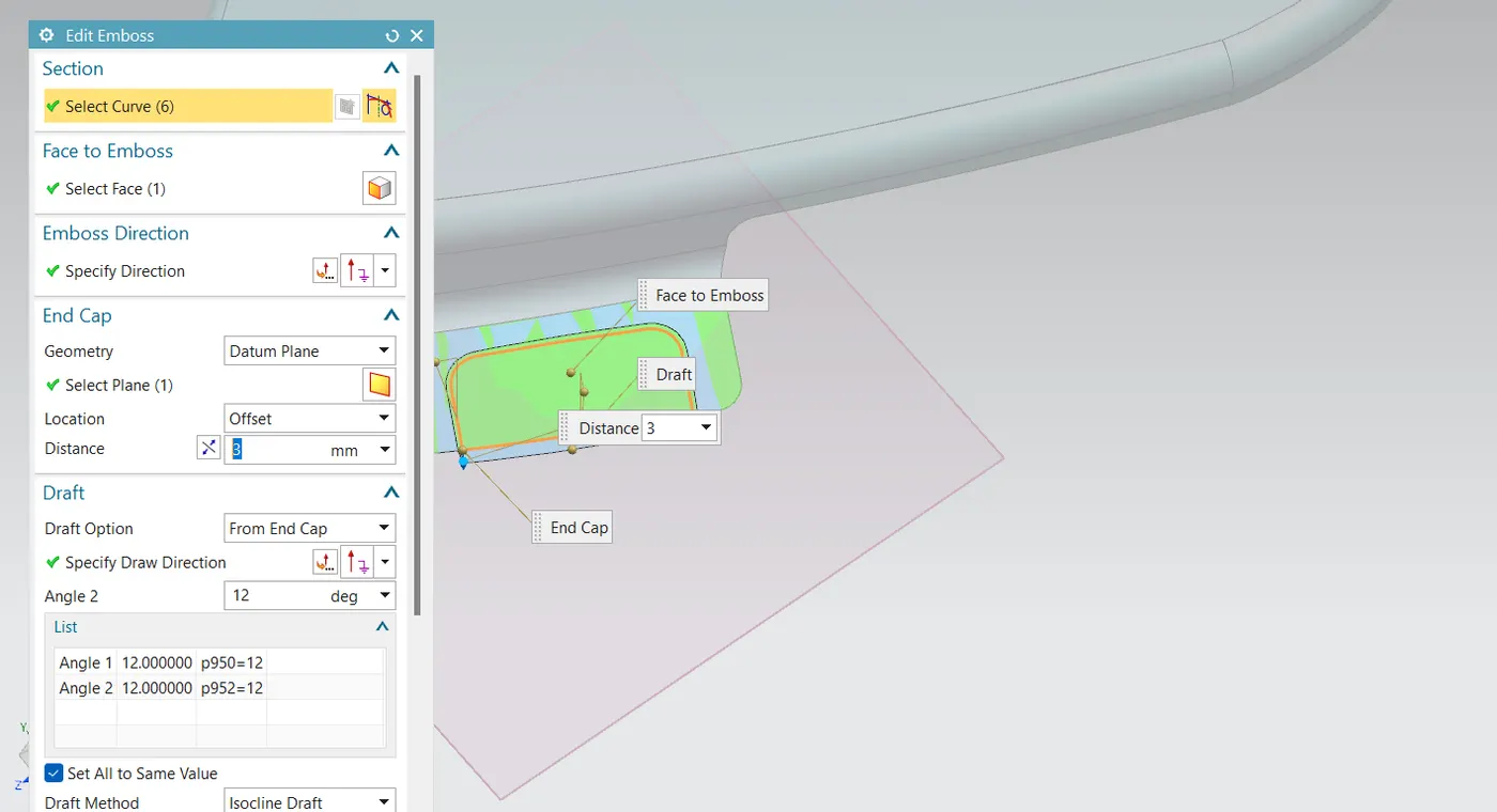
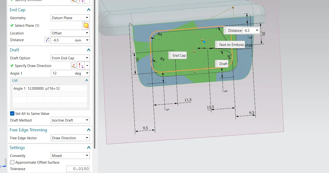
when creating each embosses we give end cap with a datum plane on the embossing surface so we will get a flat embossed surface which will give maximum area of contact when mounding
SIDE INDICATOR LAMP MOUNDING POINT
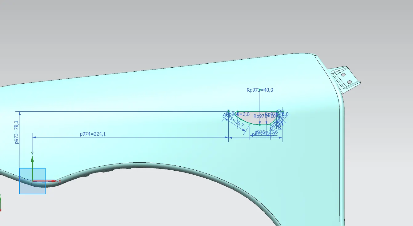
for side indicator lamp mounding we a hole with respective with the side indicator lamp. as we know the locking clips for assemblying will be on the lamp it self.
FINAL THICKENED PART
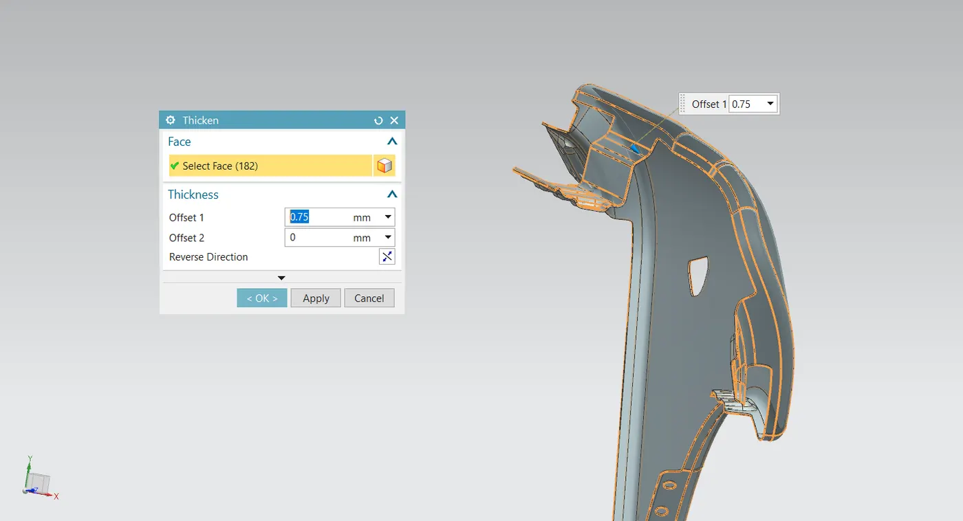
we thickend the final design in inward direction with 0.75 mm thickness.