Fender Design
Aim:
To design fender mountings by the given cad data and explain.
Fenders are essential components of various vehicles, particularly automobiles and bicycles. They serve the critical purpose of protecting vehicles from road debris, mud, water, and other hazards, preventing damage to the vehicle body and ensuring the safety of passengers. This report will delve into the design aspects of fenders, focusing on their mounts, manufacturing process, and key design parameters.
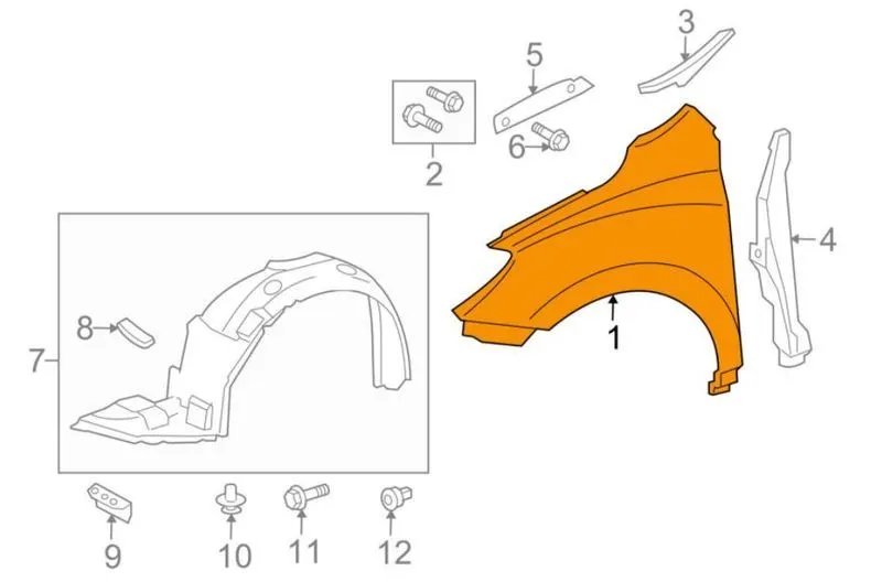
1.Fender Mounts: Fenders can be mounted to vehicles using several different methods, depending on the vehicle type and design. The most common fender mounts include:
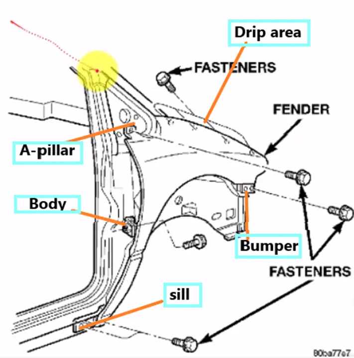
There are 5 mounting points in a fender
They are:
- Body
- A Pillar
- Sill
- Cowl
- Drip
Cowl is the plastic part, where your wiper mounting is installed.
Drip area is a region, where the fenders get contact with the engine compartment.
We use fasteners, because the fasteners regions are anyways closed. ORVM, Bumper, spoilers/sill outer that will hide the fasteners, so there is no worry for us to use fasteners here and this is not going to have any impact aesthetically. And since this also is a styling oriented part we don’t give this to suppliers mostly. We develop this part within the house (i.e. within our production unit).
Fender Drip Area:
Major and important very mounting is the drip and this is the connection of the fender with the engine compartment these are all images of fender drip areas of different cars which is used to mount on the engine compartment. As we see the pictures we can identify that design consideration is same throughout all the cars. The material is prepared in such a way that we have a standard design consideration which could be used by any OEMs. The basic consideration what we express, or the basic design consideration what we express will really be similar between all OEMs and this is fastening technique what is used to join the materials on all 5 mounting regions.
Study of fender drip area:
Drip area, as we know that this is the joining between the fender to the engine compartment, and this has a lot of design constraints to be followed. The first major thing what we got to understand is the gap from the rear end of the fender and the front end of the fender. WE have seen about cowl top part, that cowl top part will carry the wiper motor and its instruments. To have some sufficient mounting space for this cowl top, we minimum need 200mm. so when we start preparing our fender drip area, we will take this 200 mm and then we start our drip. Similarly we all know there is going to be a head lamp here. This headlamp will have an housing unit. At this housing unit, to have sufficiently placed we need atleast150 mm distance . and this length is defined with respect to the length of the fender. So we don’t have any pre-defined length on this region, but the front clearance and the rear clearance is really important. When the cowl top becomes smaller than the conventional cowl top, we can reduce the 200mm size, but on the most of the cases we have 200mm gap and 150 mm gap. So the remaining area will be our fender drip area. AND TO develop this fender drip area, we need a master section.
Other types of mountings are as follows:
a. Bolt-On Mounting: This method involves attaching the fender to the vehicle's body using bolts or screws. Bolt-on fenders are relatively easy to install and remove, making them popular among aftermarket fender options.
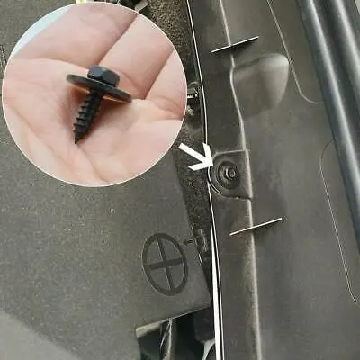
b. Clip-On Mounting: Clip-on fenders, also known as snap-on or quick-release fenders, utilize clips or other fasteners to attach to the vehicle. These are often used on bicycles and motorcycles, providing a convenient and tool-free installation.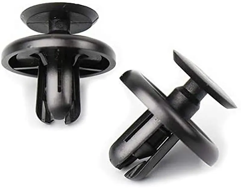
c. Stay Mounting: Stay-mounted fenders are typically seen on bicycles and involve a metal or plastic brace attached to the frame, supporting the fender's position and providing stability.
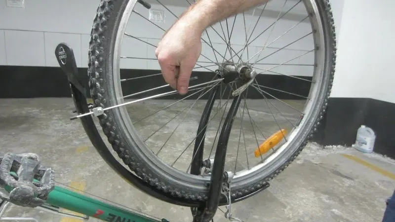
d. Full-Length Mounting: Full-length fenders run along the entire length of the wheel and are mounted securely to the frame or fork. These are commonly used on touring bicycles and some motorcycles.
2. Fender Manufacturing Process: The manufacturing process of fenders involves several steps to ensure their durability, functionality, and aesthetic appeal. The general manufacturing process includes:
a. Material Selection: Fenders are commonly made from materials like plastic, aluminum, steel, or carbon fiber. Each material has its own advantages in terms of weight, strength, and cost.
b. Mold Design and Injection Molding (for Plastic Fenders): For plastic fenders, a mold is created with the desired shape and features of the fender. Molten plastic is then injected into the mold, allowing it to cool and solidify in the desired shape.
c. Metal Forming (for Metal Fenders): Metal fenders, such as those made from aluminum or steel, undergo processes like stamping, bending, and welding to achieve the desired shape and structure.
d. Surface Finishing: Fenders are often treated with coatings or paints to enhance their appearance and protect against corrosion and environmental elements.
3. Fender Design Parameters: The design of fenders is critical for their functionality and overall performance. Several key design parameters are taken into consideration during the design process:
a. Wheel Coverage: The fender's ability to cover a significant portion of the wheel ensures effective protection from road debris and splashes.
b. Clearance: Fenders must have adequate clearance to accommodate the movement of the wheel and the suspension system without causing friction or interference.
c. Stiffness and Durability: Fenders need to be rigid enough to withstand impacts and road conditions while maintaining their structural integrity.
d. Aesthetic Appeal: Fender design also considers the visual integration of the fender with the vehicle, aiming for a cohesive and attractive appearance.
e. Weight: The weight of the fender is an important consideration, especially in applications where minimizing weight is crucial, such as in racing vehicles or high-performance bicycles.
f. Cost: Manufacturers must strike a balance between the performance and cost of fenders to make them accessible to a wide range of consumers.
Fender Skin data and designing
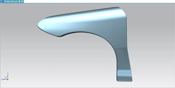
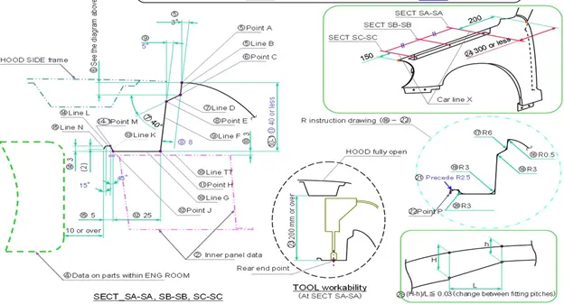
This is the master section, this will be the point what we get from the styling team and this is the fender surface what we have from the styling. After that we go 9 mm as deep as inside and we open the angle by 3deg. Why do we do this for 3 deg and why not for any other reasons we have the solution here. this 3 deg opening is given for drawing reasons. If it is less than 3 deg, If it is straight it will be difficult for production purpose. We will have to open a little. When we open this our minimum opening angle what we have to follow is 3 deg, that is how the tool will work so we give the 3 deg. How deep should we go and why it is basically 9 mm is, it is the minimum most requirement what you have to follow, when we do this, we will again have a gap and prepare an opening of 3 deg. The reason for this purpose is when you see the hood outer and the fender from the outside we will find a small gap. This gap should be the one which is preventing the visibility inside. Our design intention should be we should not see anything which looks not good inside the engine compartment. Logic is when a human protrudes inside the surface we would have create will stopped the image and you don’t see anything which is not good inside the fender drip area. Because, the fender drip area is mounted via weld nuts to the engine compartment. So it will not be good to see the fasteners from the outside, when we prepare a flange here at this dimension, we don’t allow the consumers to see the fasteners or any other not good looking area inside the engine compartment. And so that is why we create a dimension between the 7 to 8 mm. when we do this we prevent the visibility and the fender drip area distance we will have minimum of some value between35 to 40. This 35 to 40mm reason is for the tool to come and work perfectly inside. We will open the hood and mount our fender and then fix it with the help of weld nuts. So which means, the assembly sequence is we have car body without the hood and first we will mount our hood on the hinges, and we keep the hood in open condition and then we mount the fender with the help of the tool and to axes this tool we need at least 200 mm gap. When we have hood in open condition we definitely have 200 mm condition. this is just a reference for us. And the landing area is also the minimum most required surface to meet inside the engine compartment. So this is how we prepare the drip area and this is given to add strength, an empty surface is more witherable, when we give an emboss or structure there we strengthen the part but we should make sure that there is no other part inside the engine room at least for 10 mm. if we have this passed, we can exceed the drip area. So our basic requirement is the end most part which will be in contact with the fender drip area should have at least 10mm clearance so that we don’t hit or damage while assembling the part. while assembling the commodity inside the engine room. And then with respect to this, we vary the values in fender drip area.
Hood side drip depth must be 40mm because the tool which is producing our part will have the tendency to punch this deep and if it goes more than this, it will be difficult for punching it. We have a big material and we are going to punch and it cannot go more than 40 mm most of the times(majority of the times). There are some tools which are capable of doing only till 30 mm, yes we can also do that, the more deeper , the more difficult the part is, so this is a kind of optimum value where most of the cases is achieved, if it exceeds more than 60 mm we tend to get a spring back effect. We have to assure that the part should not produce any spring back effect. Out of parent car and experience we have we detect this value.
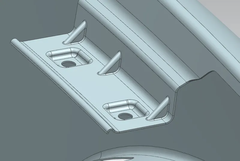 Fig shows drip area.
Fender wheel arch area:
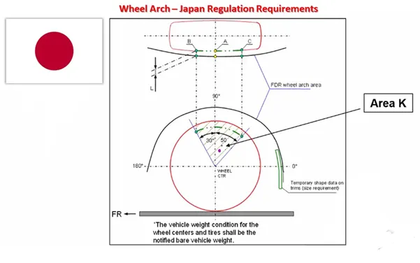
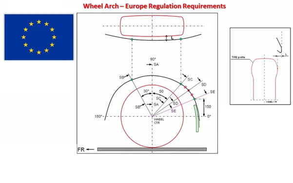
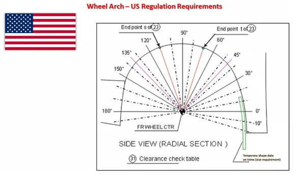
Now, we are going to see three major regulations of the regions on Wheel arch as these three markets are concentrated highly in the market. Because the other regional regulations come with requirements in preference and mostly along these three regulations.
Japan Regulations Requirement:
- Measure clearance L of tire, hub, cap and fender in three different positions within area K and produce clearance check chart to validate.
- Clearance must be greater than 5 mm in all the three positions.
- Wheel guard requirement: The value of ‘a’ shall be more than 5 mm at a line 30deg forward and 50deg rearward from the central vertical axis of axis of wheel.
European Regulations Requirement:
Measure CL L at sections SA-SA SB-SB SC-SC SD-SD SE-SE and produce CK check chart to validate.
- At all five sections the CL L value should be greater than 10 mm to satisfy the European regulations.
- Wheel guard requirement: the value of ‘a’ shall be more than 5mm at a line 30deg forward and 50 rearward from the central vertical axis of axis of wheel.
US Regulations Requirement:
- Make clearance check details on all positions from – 100deg to 100deg and make the clearance check table.
- All values should be greater than 5mm to satisfy the regulations.
- The value of ‘a’ shall be more than 5mm at a line 30deg forward and 50deg rearward from the central vertical axis of axis of wheel.
Then we designed the A-Pillar mount, Sill mount, Baffle mounts and Bumper Mount with our own designs as the drip area region is only provided with the master section. I just leaved this fender design without an indicator light section in fender as today cars are getting it in ORVM itself, it also reduces cost. So I designed this fender without indicator light cutout just to reduce cost.
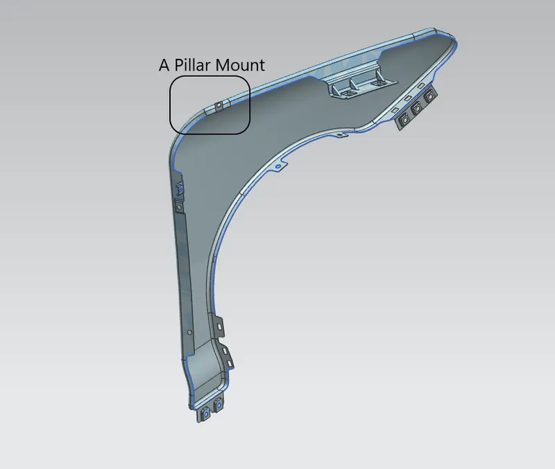 Fig shows A pillar mount
Sill Mount:
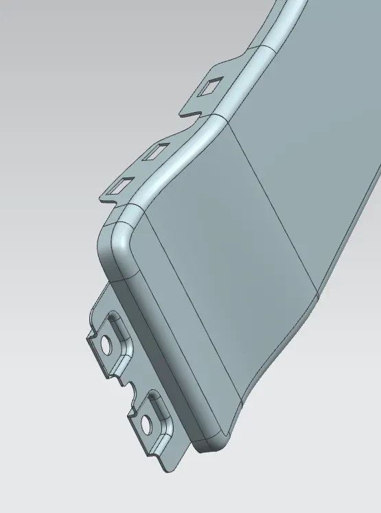 Fig shows Sill Mount
Bumper Mount:
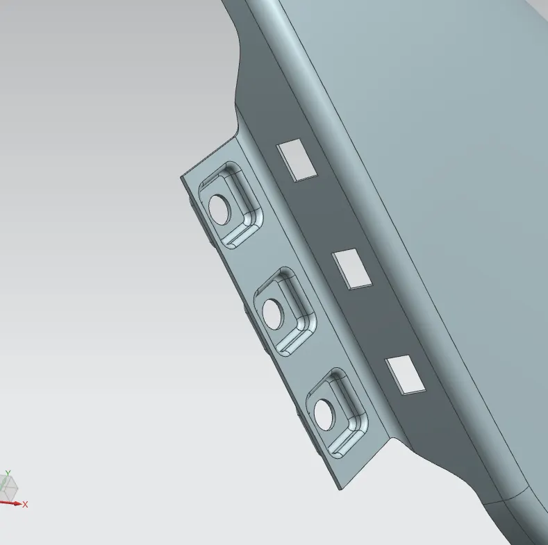 Fig shows Bumper Mount
There is Mounting on upper side are provide for Bumper bracket mount.
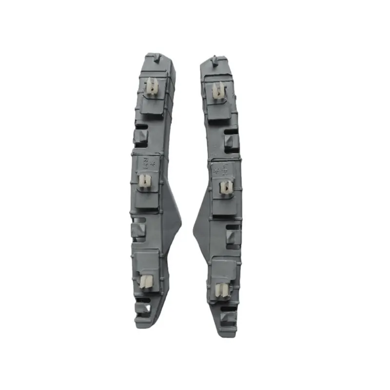
Baffle Mounts:
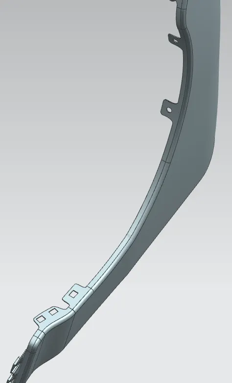
fig shows buffle mount also holes are provided for mud flap mounting at bottom. baffle is mounted using clipping method where push clips are used so according to that holes are provided.
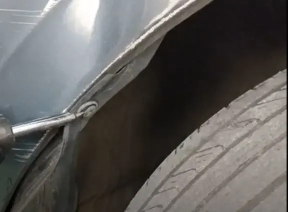
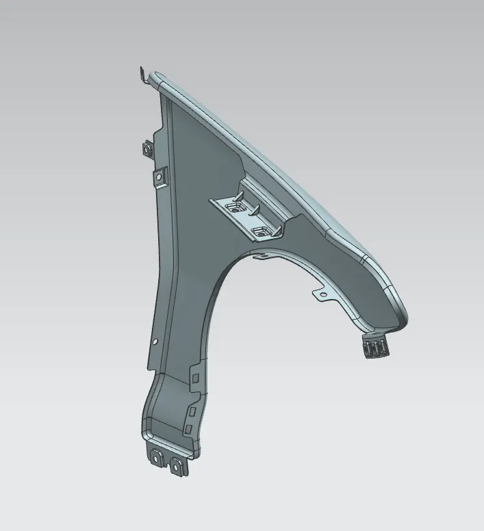
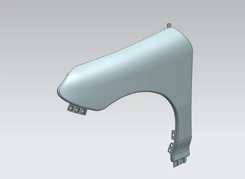
Our Front Fender Model:
Conclusion: In conclusion, fenders play a vital role in protecting vehicles from road hazards, and their design, mounting methods, manufacturing process, and key parameters are crucial in ensuring their effectiveness. Understanding these aspects is essential for engineers, designers, and manufacturers to produce reliable and high-quality fenders that meet the needs of various vehicles and their users.