Fender Design
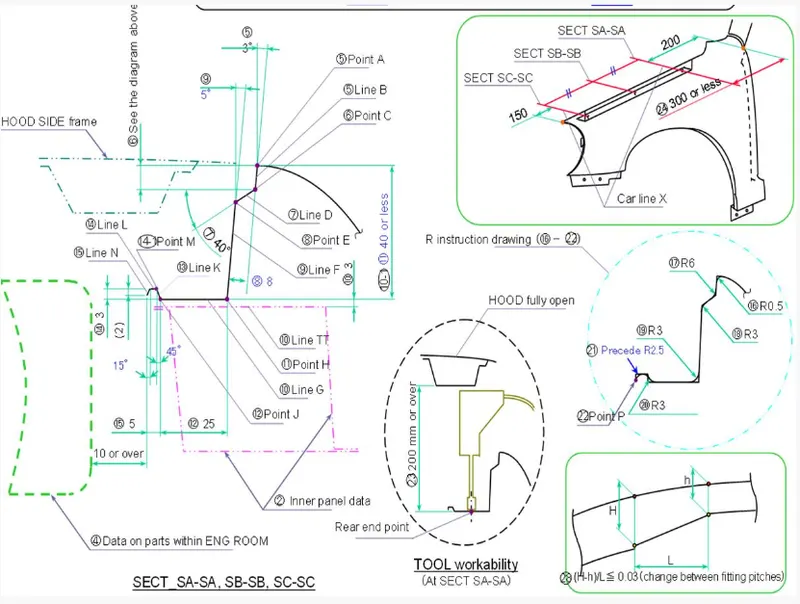
AIM: - Create a front fender using the provided skin data and the master section, which includes Drip mounting, A-pillar, Sill, Bumper, and Baffle (splash) Mounts.
GIVEN MASTER SECTION
INTRODUCTION
A fender is a car's front outer side part that covers the wheel side. A fender aims to keep sand, dirt, pebbles, liquids, and other particles out. The fender is a component that closes the engine compartment and adjacent compartments. The primary function of the fender is to prevent chipping within the engine compartment. During motion, the wheel gathers up sand, dirt, and small stone particles and sends them into the automobile, where these fenders will assist prevent them from reaching the engine compartment and car body. These fenders will feature a plastic piece on the wheel arch region. The fender also plays an important function in avoiding issues for pedestrians. Fenders are normally stiff and can be damaged by road surface contact. Mudguard is another name for it. The term "fender" refers to the section of a vehicle's body that frames a wheel inside it. Its major role is to keep rotating tyres from throwing sand, dirt, liquid, and other debris into the air. Fenders are normally stiff and can be damaged by road surface contact. Sticky materials, like mud, may attach to the smooth outer tyre surface, while soft loose items, like stones, may become momentarily lodged in the tread grooves when the tyre rolls over the ground. As the tyre imparts kinetic energy to the connected items, these materials can be expelled off the surface of the tyre at high velocity. The top of a moving vehicle's tyre rotates upward and forward, throwing things into the air at other cars or people in front of the vehicle.
TYPES OF FENDERS
1. FULL BUMPER TYPE
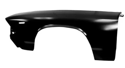
These fenders were found on older generations of automobiles. They contribute significantly to the increase in steel weight by simply shielding the front headlamps about the bumper region. The issue with this type of fender is that there is a lot of waste in the blank, and every inch of material costs the business money.
2. HALF BUMPER TYPE
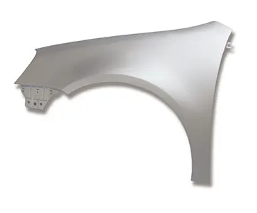
These fenders are mostly employed for cost-cutting and decreasing enough proportions of the steel weight, leading to a modest weight reduction of the car. They can be produced inexpensively, as we may print two fenders at a time by just expanding the blank size.
MANUFACTURING PROCESS USED FOR FENDER SHEET METAL
BENDING
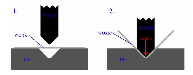
Bending is the application of force to a sheet metal workpiece to generate a surface curve. Bending is typically utilised to create basic curved surfaces rather than complicated curved surfaces. A mechanically controlled press pushes a punch into sheet metal, pressing it into a basic die with enough force to permanently change the form of the metal. The quantity of pressure is critical. If not enough force is exerted, the metal will simply return to its previous shape. It can break if too much pressure is applied.
DRAWING
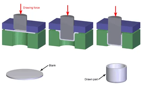
Drawing involves pressing sheet metal against a die that has been carved into the three-dimensional, generally curved shape that the sheet metal will take on. In effect, the die serves as a metal mould. This technology is capable of producing quite intricate forms. Once again, a hydraulically or mechanically driven punch is used to provide pressure on the workpiece. There are a variety of risks involved, not so much to people (since the process is mostly automated), but to the metal itself. It can break as a result of too much pressure or wrinkle as a result of its interaction with the die. Lubricant can be applied to make the metal glide more smoothly against the die, preventing wrinkling.
STAMPING
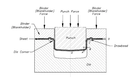
A stamping press is used with a set of dies to cut and mould metal into various forms in stamping. This is extensively used in the manufacture of automobile components like hubcaps and fenders.
EXTRUSION
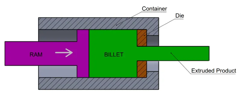
Long metal items, such as rods and tubes, can be produced via extrusion. The metal workpiece is pressed into a die with a hole at one end. To construct the shape, the metal is extruded through the hole. Extrusion can be used to make critical components of a car's drive train, such as seatbelt anchors.
FORGING
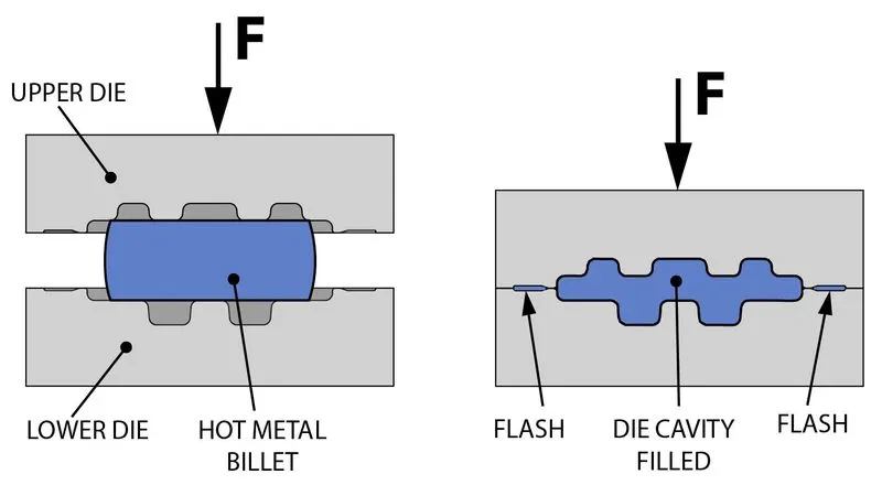
A hammer or press is used in the forging process, which is essentially a mechanised replica of the hammers used by ancient blacksmiths. The metal is pounded against an anvil-like surface. It may be repeatedly hammered to make complicated forms. This might be used as a substitute for drawing.
MOUNTING REGION ON FENDER
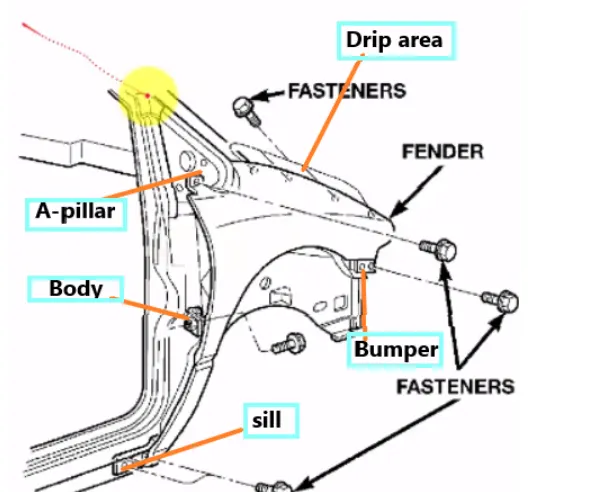
DRIP MOUNTING AREA
This section is installed beneath the hood's inner panel, which must be flush when the hood is closed and have as few gaps as possible. The drip region is either spot welded or fastened down with self-tapping screws in some circumstances.
SILL MOUNTING AREA
The sill is the panel right under the bottom of the door that supports the floor and can be utilised to connect the floor and the body. For strengthening of the fender panel, the bottom end of the fender is attached to the sill body, therefore the sill mounting location is provided with holes and emboss. To secure the fenders to the sill body, M5 fasteners are employed.
A-PILLAR MOUNTING AREA
The A-pillar area mounting is determined by the car's A-pillar. Ribs can be added to reinforce the component. This mounting is crucial in design since it must be appropriately positioned on the A-pillar.
BUMPER MOUNTING AREA
The bumper mounting area is utilised to secure the plastic bumper to the fender using screws.
BAFFLE MOUNTING AREA
Baffle mounting or mudguards are clip-on mountings that go on the inside side of the fender arch above the tyre. When the automobile is in motion, it protects the engine compartment and pedestrians from being injured by chip-out objects on the road. They are attached to the fender with a unique sort of locking clip made of plastic.
CREATION OF FENDER MOUNTING AREA
CREATION OF DRIP MOUNTING AREA
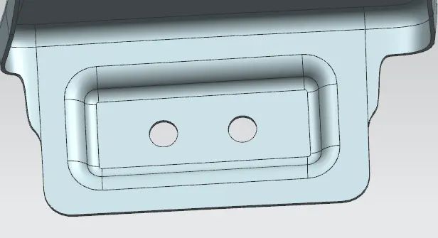
- The drip area is designed with a 150mm clearance from the front end for headlamp fittings and a 200mm clearance from the rear end for the wiper motor assembly (Cowl top region).
- To eliminate the spring-back effect, the drip area is kept at a depth of less than 60mm.
- Ribs are installed at the fender drip region to boost strength.
STEP 1: Use law extension from the flanges specified in the master section.
STEP 2: Blend the faces of all the law-extended flanges.
STEP 3: Sketch the mounting area face and 5 mm dia holes with a smooth surface of 10 mm dia.
STEP 4: Project the sketch onto the drip area surface.
STEP 5: Make a datum plane to offer that respect emboss.
STEP 6: Apply a 3.5 mm emboss.
STEP 7: Cut holes in the sheet.
STEP 8: Emboss the facial blending.
STEP 9: Make a dart in the centre of two embosses.
STEP 10: Apply an edge fillet to ensure that there are no sharp edges and that the surfaces transition smoothly.
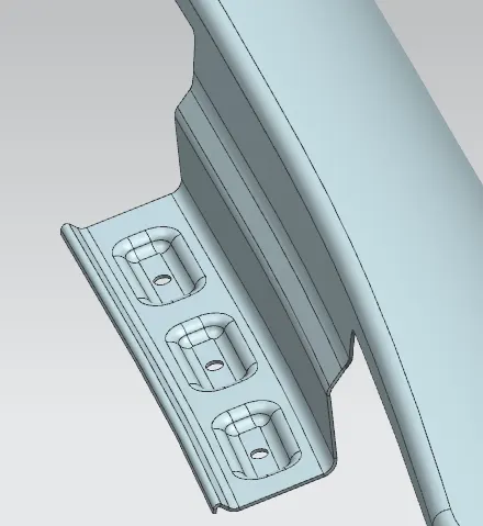
CREATION OF SILL MOUNTING AREA
STEP 1: Extend the fender sheet from the border of the sill region.
STEP 2: Draw a datum plane perpendicular to the enlarged surface.
STEP 3: Sketch the mounting area face and 5 mm dia holes with a smooth surface of 10mm dia.
STEP 4: Create an emboss of 3.5mm with an end cap similar to the plane we made before.
STEP 5: Cut holes in the sheet.
STEP 6: Emboss the facial blending.
STEP 7: Bridge the curve on the sheet to eliminate sharp edges.
STEP 8: Trim the sheet with bridge curves, making sure there are no sharp edges and that the surfaces transition smoothly.
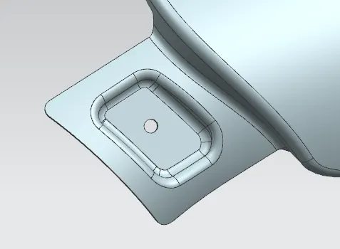
CREATION OF A-PILLAR MOUNTING AREA
STEP 1: Use law extension to the enlarged sheet's two corners.
STEP 2: Trim the sheet so that there are no sharp corners.
STEP 3: Draw a datum plane concerning the enlarged surface, a few millimetres above the surface, and choose the sketch orientation.
STEP 4: Sketch the mounting area face and 5 mm dia holes with a smooth surface of 10mm dia.
STEP 5: Project the sketch onto the surface of the A-pillar region.
STEP 6: Make a new datum plane about the enlarged surface.
STEP 7: Create an emboss with an end cap similar to the plane we made before.
STEP 8: For holes trim the sheet.
STEP 9: Apply face blends to emboss, ensuring that there are no harsh edges and that the surfaces transition smoothly.
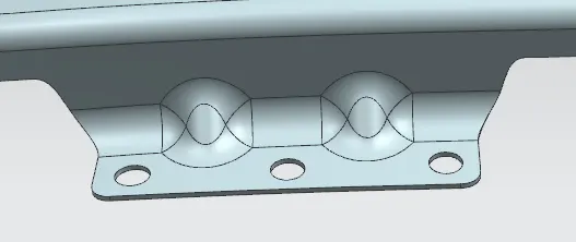
CREATION OF BUMPER MOUNTING AREA
STEP 1: Use Law Extension to the 90 degrees of the face and 15 mm in length.
STEP 2: Bridge the curve to the enlarged sheet's two corners.
STEP 3: Trim the sheet so that there are no sharp corners.
STEP 4: On the extended sheet and fender flange, create a dart.
STEP 5: Apply a 5 mm edge blend.
STEP 6: Draw a datum plane concerning the enlarged surface, a few millimetres above the surface, and choose the sketch orientation.
STEP 7: Sketch the mounting area face and 5 mm dia holes with a smooth surface of 10mm dia.
STEP 8: For holes trim the sheet.
CREATION OF BAFFLE MOUNTING AREA
STEP 1: Move the curvature of the face blend edge down 5mm.
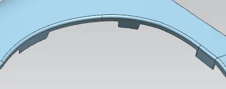
STEP 2: Create a bridge curve from the offset curve to the fender's edge to exhibit a seamless transition of the surface after trimming at three different parts of the fender to produce baffle mounting.
STEP 3: Trim the surfaces as shown in the illustration below.
STEP 4: Draw a plane a few millimetres above the fender's surface.
STEP 5: Draw two circles of 5 mm dia, with a 10 mm dia smooth surface and a considerable gap between them.
STEP 6: Bring the drawing to life on the surface.
STEP 7: Trim the sheet to reveal the baffle holes.
STEP 8: Repeat for the remaining two baffle regions, as illustrated in the image below.
STEP 9: Thicken the Fender Part.
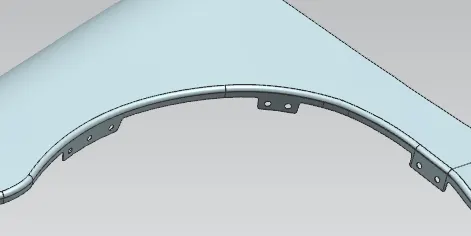
Various orientations of Fender's final design
FRONT VIEW
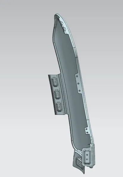
RIGHT HAND SIDE VIEW
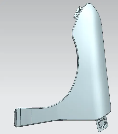
LEFT HAND SIDE VIEW
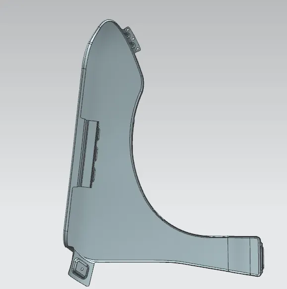
TOP VIEW
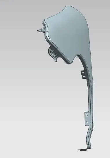
ISOMETRIC VIEW
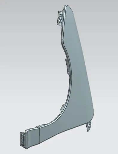
CONCLUSION
Finally, the design of Fender is done with the help of NX-CAD software by following the master section.