Fender Design
FENDER DESIGN
AIM: To design a front fender of a car by following the given master section as per the design considerations of OEM.
INTRODUCTION :
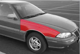
Fender is the american english term for the part of an automobile, motorcycle, or other vehicle body that frames a wheel well. Its primary purpose is to prevent sand, rocks, mud, liquids, and other road spray from being thrown into the air by the rotating tire. Fenders are typically rigid and can be damaged by contact with the road surface. Sticky materials, such as mud, may adhere to the smooth outer tire surface, while smooth loose objects, such as stones, can become temporarily embedded in the tread grooves as the tire rolls over the ground. These materials can be ejected from the surface of the tire at high velocity as the tire imparts kinetic energy to the attached objects. For a vehicle moving forward, the top of the trie is rotating upward and forward and can throw objects into the air at other vehicles or pedestrians in front of the vehicle. A fender is a front outer side member of a car, which covers the wheel side. It has so many small features with ups and downs.
FENDER
It is an aesthetic component/part of a car that frames the wheels. The main purpose of the fenders is to prevent sand, mud particles, and other road contaminants from being thrown into the engine compartment and to pedestrians by rotating tires.
TYPES OF FENDERS
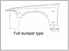
1. FULL BUMPER TYPE: These types of fenders were used in earlier models of vehicles. They contribute to the major increment of the steel weight by just covering the front headlights concerning the bumper region. The problem with this kind of fender is a lot of waste in the blank and every inch of a material is a cost to the industry.
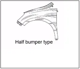
2. HALF BUMPER TYPE: These fenders are mainly used for serving the purpose of cost-cutting and reducing enough proportions of the steel weight resulting in a reduction of the weight of the vehicle slightly. They can be economically manufactured, i.e. by slightly increasing the blank size, we can produce two fenders at a time.
MOUNTING REGIONS ON FENDER :
PURPOSE OF THE FENDER :
ENGINE SAFETY: Protect the engine, occupants, and passers-by from items, water, mud, snow, and ice, thrown off the tires as you drive.
PEDESTRAIN SAFTEY: Protects pedestrians from the wheel, e.g. it's better to be it by a laterally moving fender than a rolling tire, and keeps loose, streaming items from being wrapped up in a rolling wheel.
AEWRODYNAMICS: Smooths the car profile so you don't get a lot of drag off the uncovered wheels. Some fenders are enclosed on the side for this.
GOOD CAR APPEARANCE: Looks better with Fender, gives a finished look, and looks more streamlined.
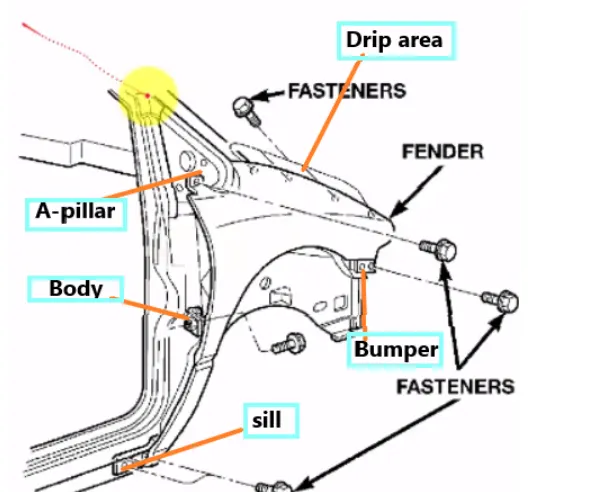
There are 5 mounting regions on the fender as follows-
1. Drip Area
2. A-Pillar Mounting Area
3. Sill Mounting Area
4. Bumper Mounting Area
5. Baffle Mounting Area
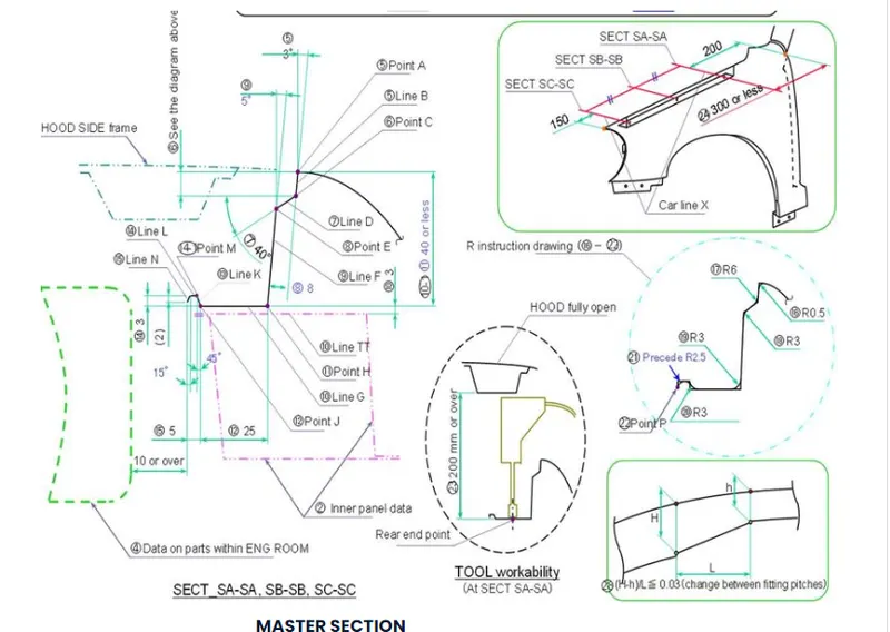
MaSTER SECTION (Given data):
Basic Construction
First, join the given Classy surface then we create the curves on the Boundry side of the joined surface for the flange
we create the flanges for the Different mounting Areas like
1. Drip Area
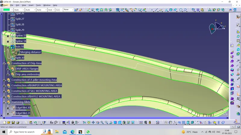
2. A-Pillar Mounting Area
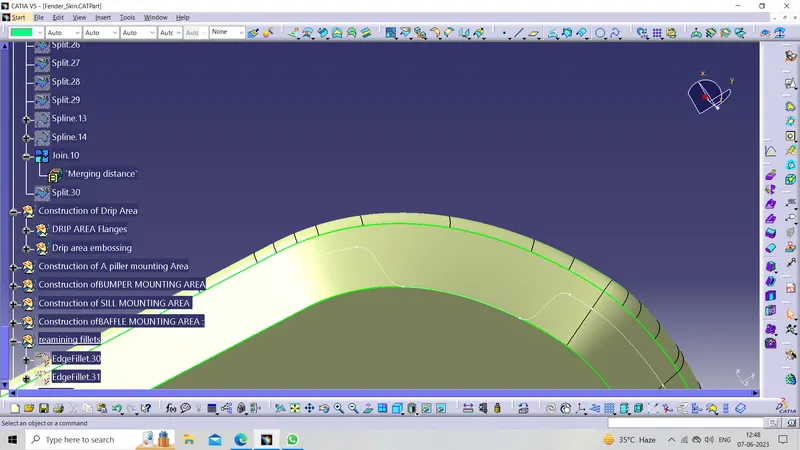
3. Sill Mounting Area
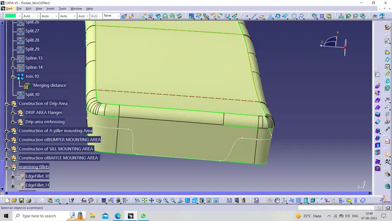
4. Bumper Mounting Area
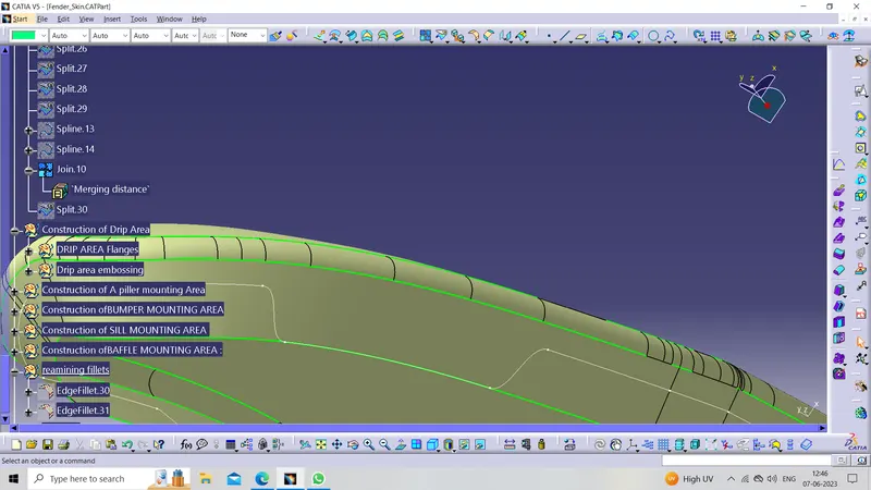
5. Baffle Mounting Area
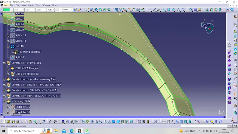
Now splitting the Working surface with the created Curve
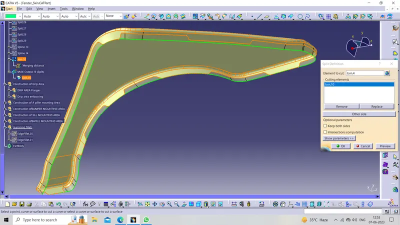
Now one by one create the mounting Area on the Above surface
1. DRIP AREA :
Drip area mounting is an important part of the fender. this mounting is attached to the engine compartment of the car. fender drip area is mounted via weld nuts to the engine compartment. a min of 150mm distance is kept from the front side and a distance of 300mm or less can be kept on the rear side. the total length of the drip area from the top of the fender should be less than 40mm, this is to avoid the spring back during the manufacturing. the edge of the mounting should be at least 10mm away from any nearby component in the engine. a rigidity bead is provided at the end to increase the strength of the mounting.
The flange for the drip area is already created above now using the edge of the Drip area flange creating the sweep as per the given master section
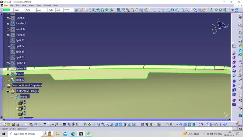
Now create a sweep at 45 degrees For 8 mm
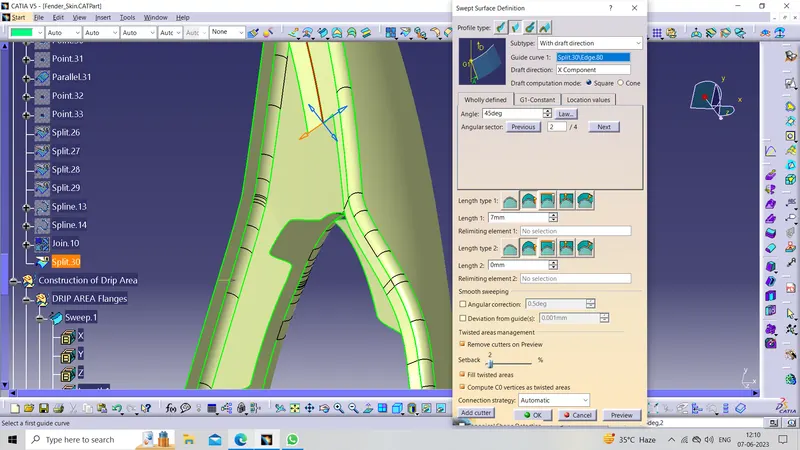
Now create a sweep at 15 degrees For 15 mm From the edge of the above sweep
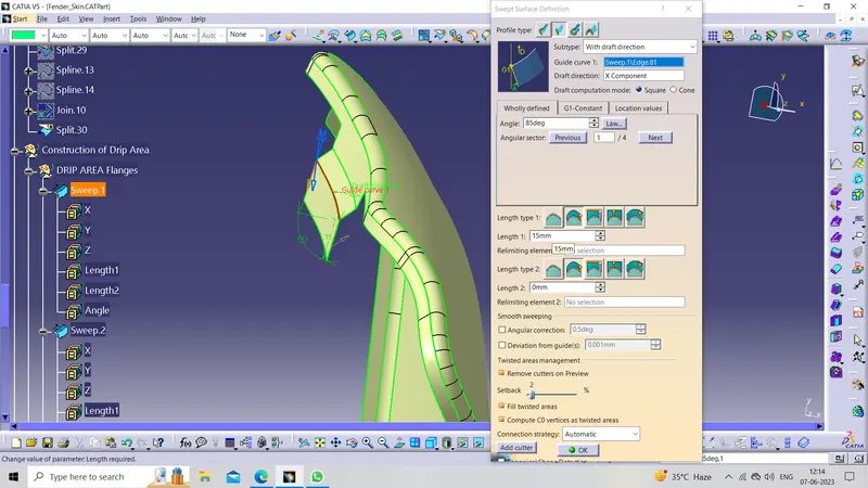
Now create a sweep at 0degrees For 25 mm From the edge of the above sweep
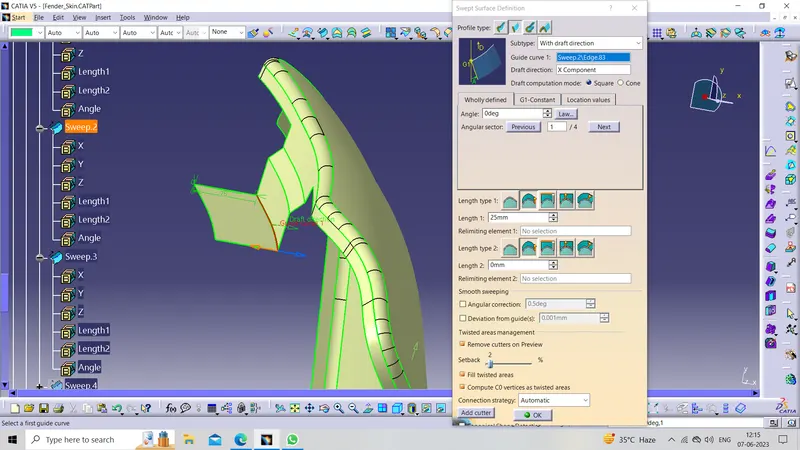
Now create a sweep at 45 degrees For 4.25 mm From the edge of the above sweep
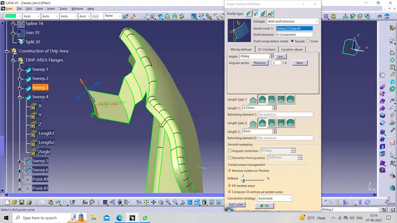
Now create a sweep at 0 degrees For 1.5 mm From the edge of the above sweep
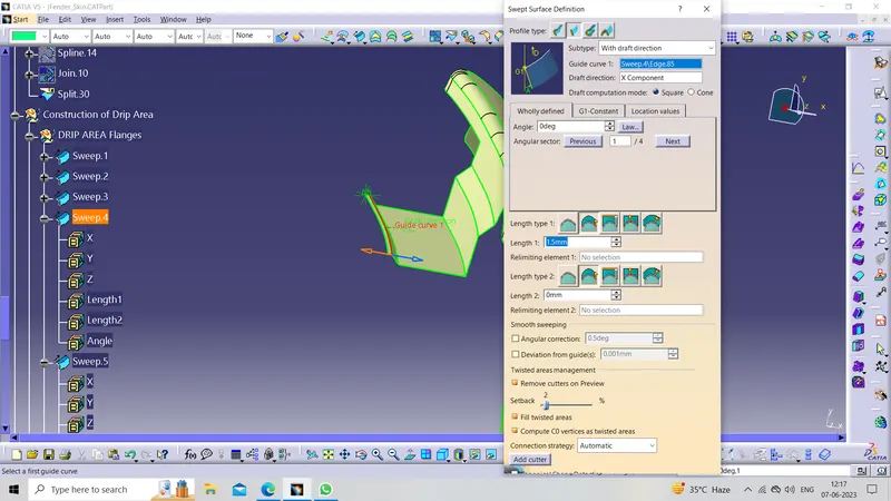
Now create a sweep at 75 degrees For 2.117 mm From the edge of the above sweep
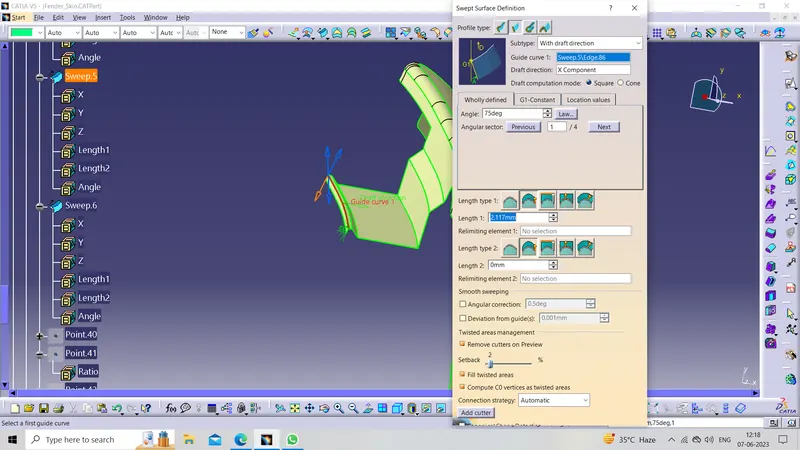
Now creating
DART :
By using the Bead command from the Generative shape design Workbench Darts are provided at the bend to reduce the shakiness caused by the vibration of the engine of the mounting area and stiffen the area. It is specially provided in the larger area.
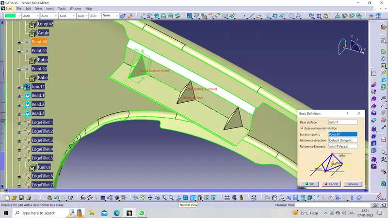
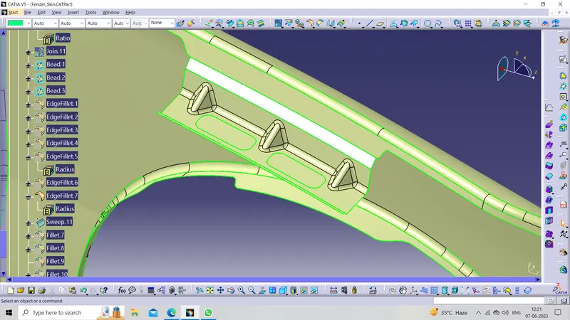
Now creating the sketch for Embossing And Holes for the Fasteners
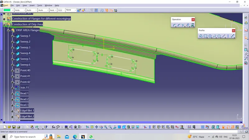
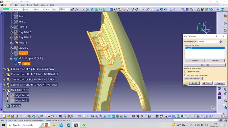
Now project the Above sketch on the working surface then split it
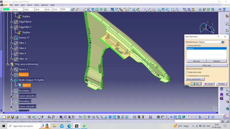
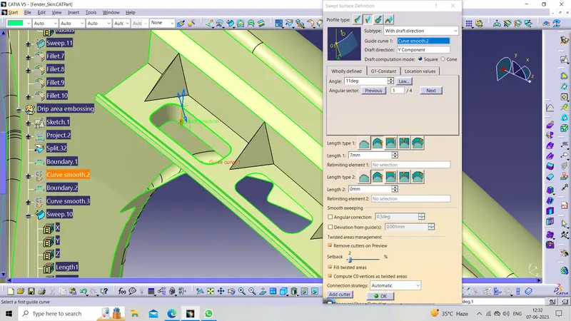
Now create the sweep on the split area at an angle of more than 7 degrees
Now create a flat offset surface for the base of Our Emboss then trim it with the sweep
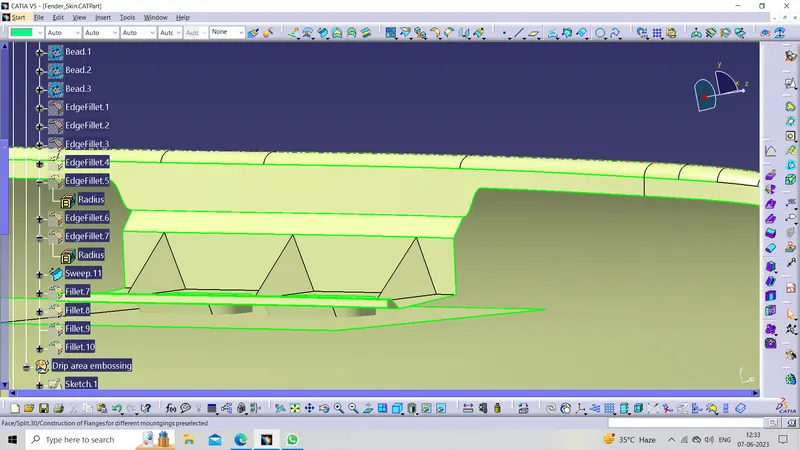
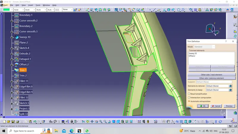
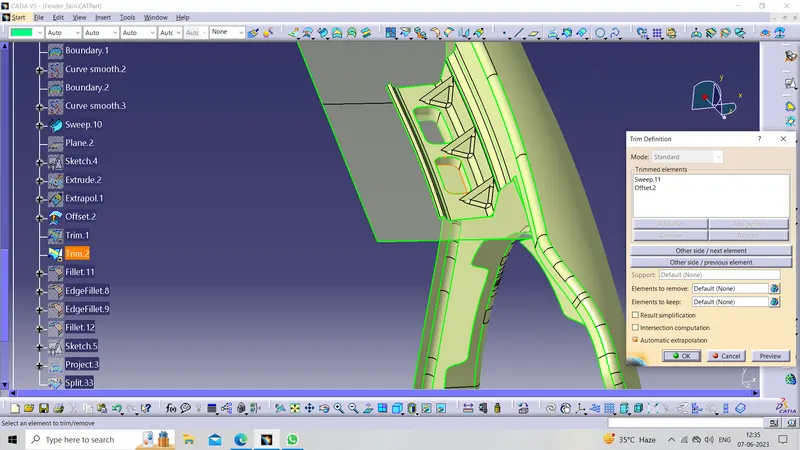
Now create a sketch for holes Then split it
2. A PILLER MOUNTING AREA :
The A-pillar area mounting depends upon the A-pillar of the car. the mounting can also be provided with ribs to strengthen the part. this mounting is critical in design as it has to be mounted on A-pillar properly.
Firstly Sweep the edge of the flange which is perpendicular to the Flaneg
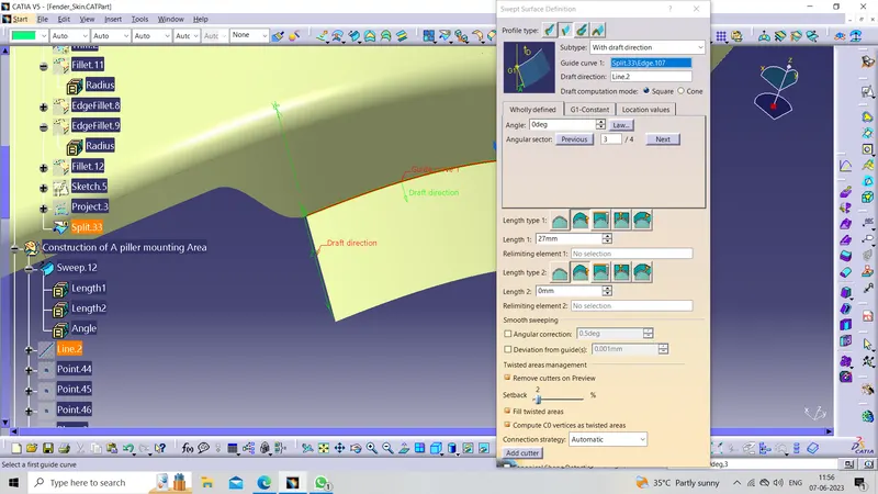
Now creating the sketch for Embossing And Holes for the Fasteners
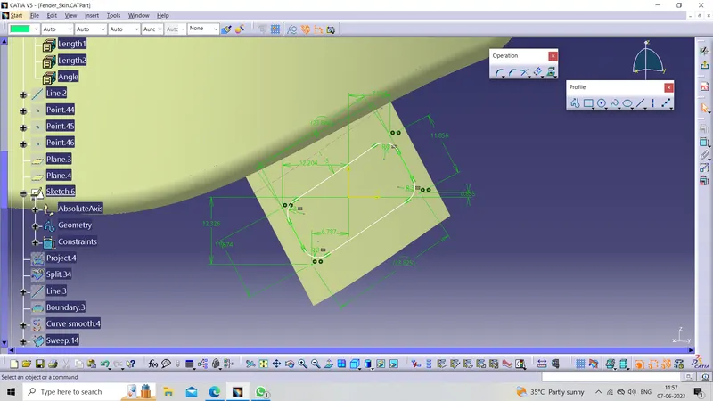
Now project it on the Working surface by using the Project 3d command And then split it with the working surface
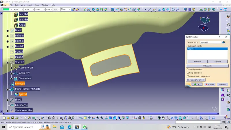
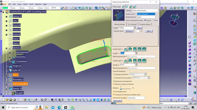
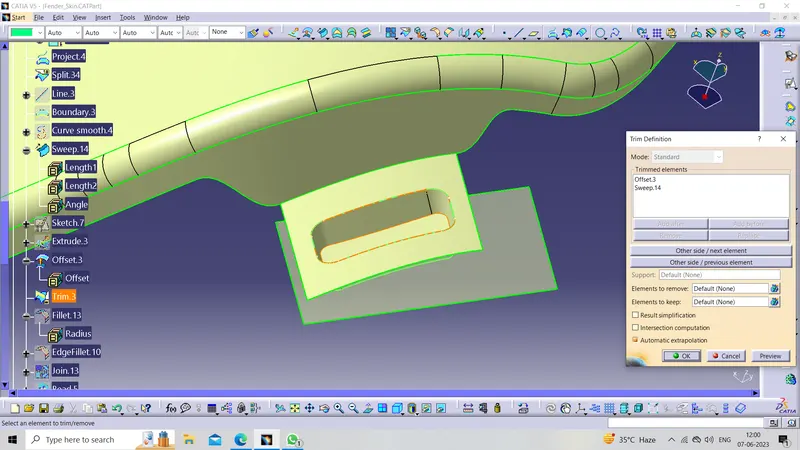
Now create the sweep on the split area at an angle of more than 7 degrees
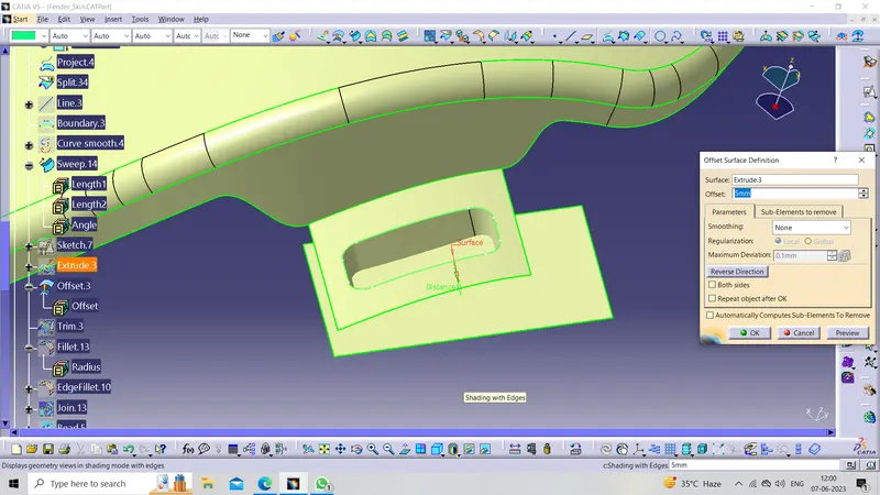
Now create a flat offset surface for the base of Our Emboss then trim it with the sweep
Now creating
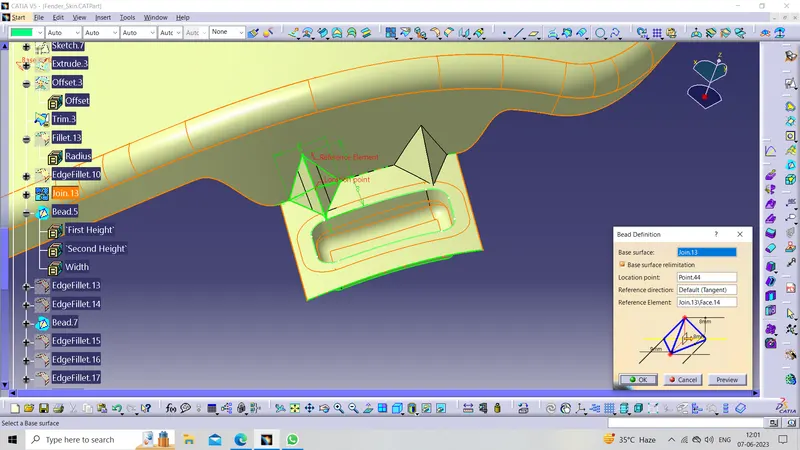
DART :
By using the Bead command from the Generative shape design Workbench Darts are provided at the bend to reduce the shakiness caused by the vibration of the engine of the mounting area and stiffen the area. It is specially provided in the larger area.
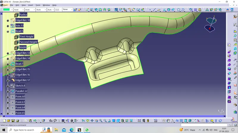
Removing the sharp edges
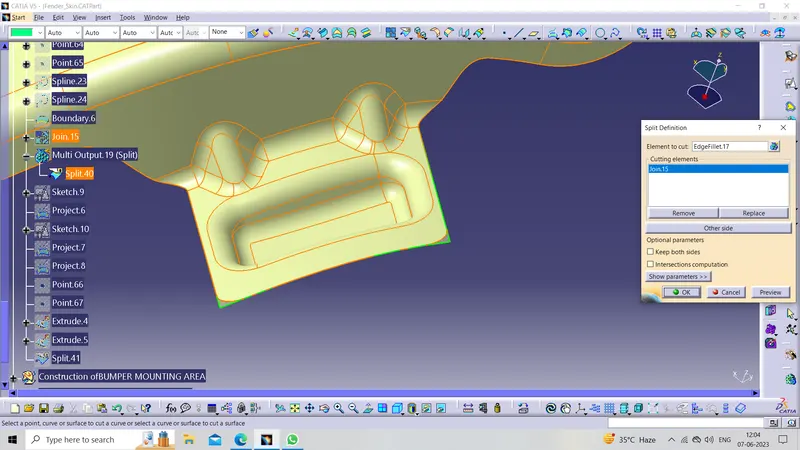
Now create Sketch for Holes And then project the sketch
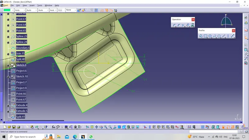
Now Split the above with the working surface
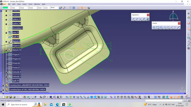
Now split the above sketch with the working the surface
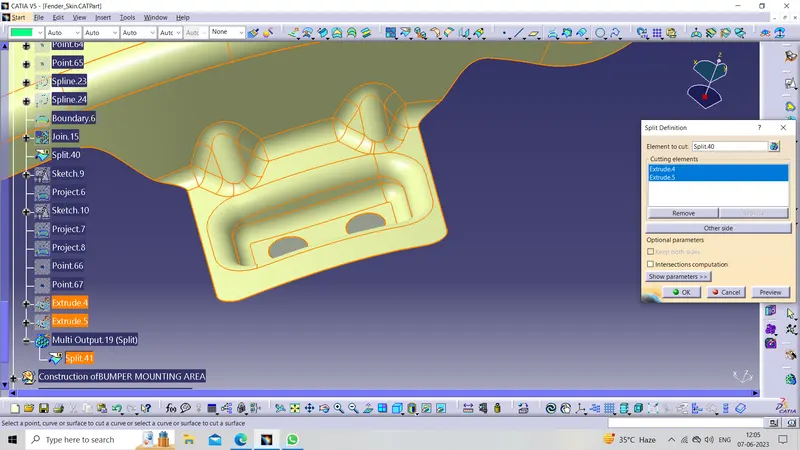
3. SILL MOUNTING AREA :
The area at which the bottom of the fender gets connected to the floor near the bottom edge of the door. The Embossed sill mounting of the fender is attached To fasteners.
Extrapolating the Sill mounting Area flange suitable clearance
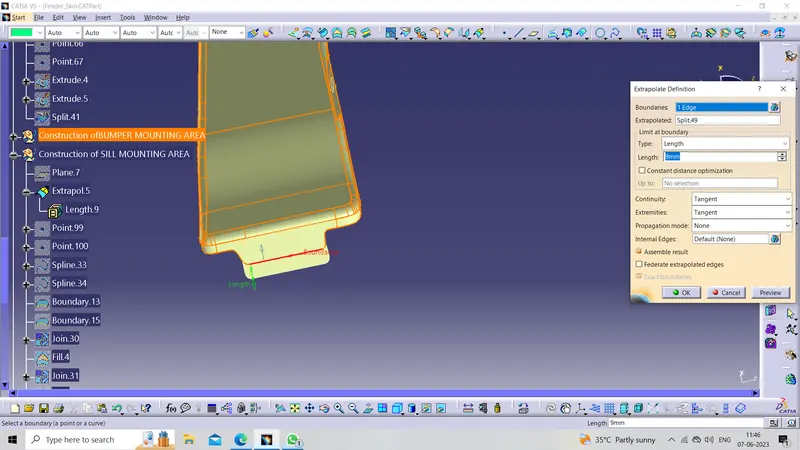
Now create the sketch for Embossing then project it on the working surface and then split it from the working surface
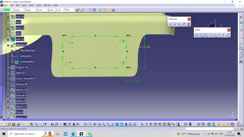
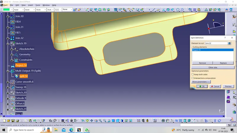
Now create the sweep on the split area at an angle of more than 7 degrees
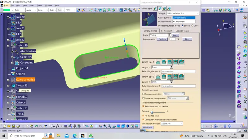
Now create the 5mm flat offset surface And then trim it with the sweep for the base of the Embossing 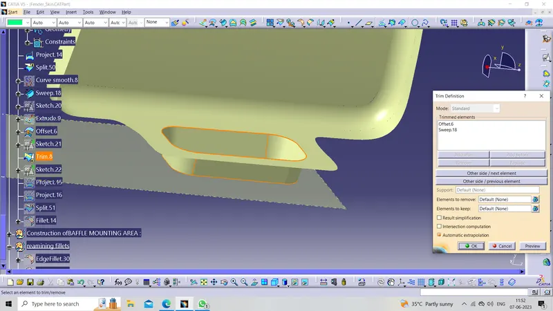
Then create the sketch for holes then split it with the working surface
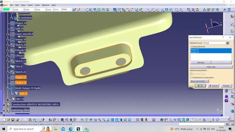
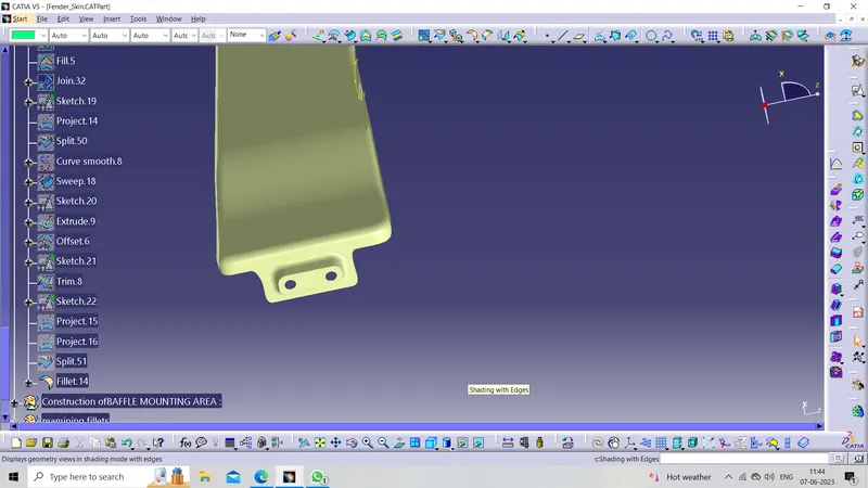
4. BUMPER MOUNTING AREA :
The bumper mounting area is used to fix the plastic bumper to the fender with the help of the fasteners For that we have created the Emboss And Dart
Firstly Sweep the edge of the flange which is perpendicular to the Flaneg
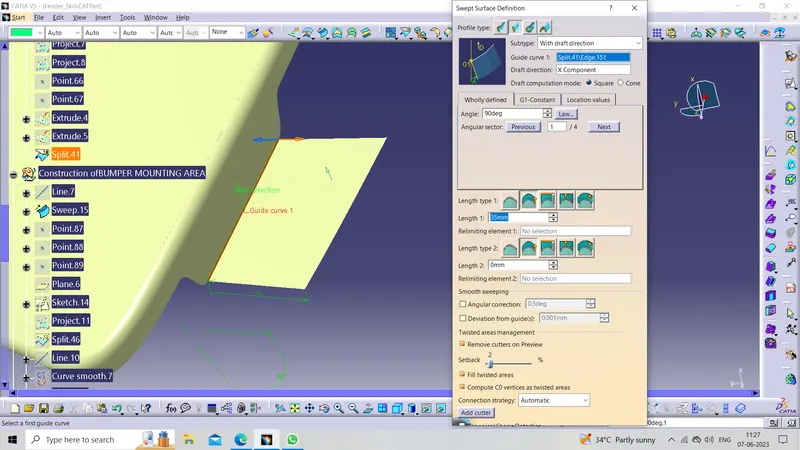
Now creating the sketch for Embossing And Holes for the Fasteners
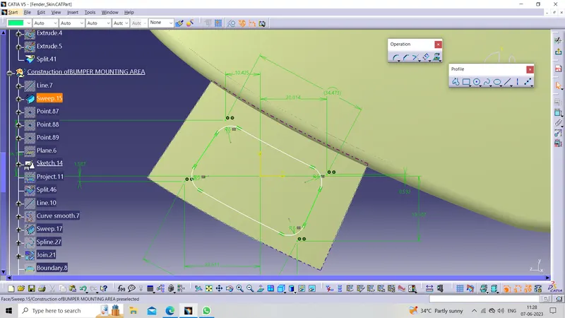
Now project it on the Working surface by using the Project 3d command And then split it with the working surface
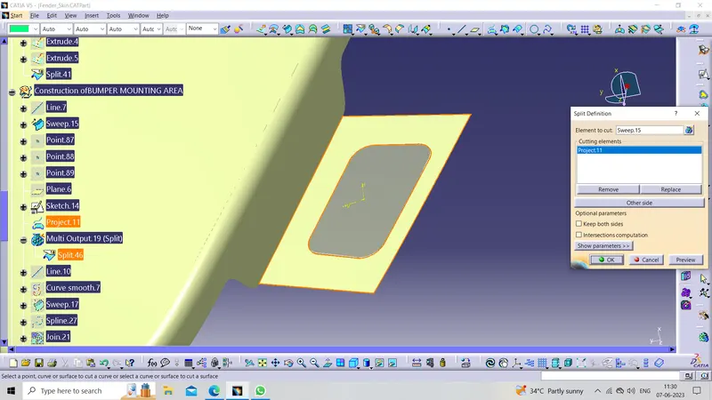
Now create the sweep on the split area at an angle of more than 7 degrees
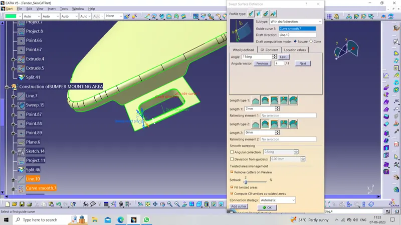
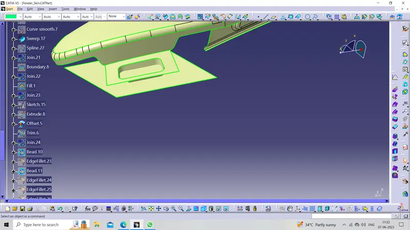
Now create a flat offset surface for the base of Our Emboss then trim it with the sweep
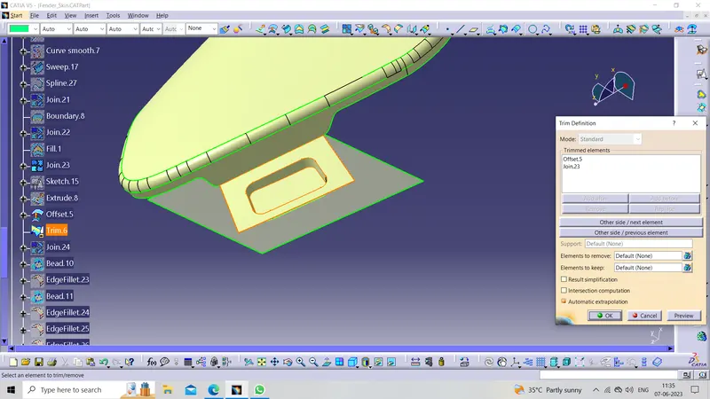
Now creating
DART :
By using the Bead command from the Generative shape design Workbench Darts are provided at the bend to reduce the shakiness caused by the vibration of the engine of the mounting area and stiffen the area. It is specially provided in the larger area.
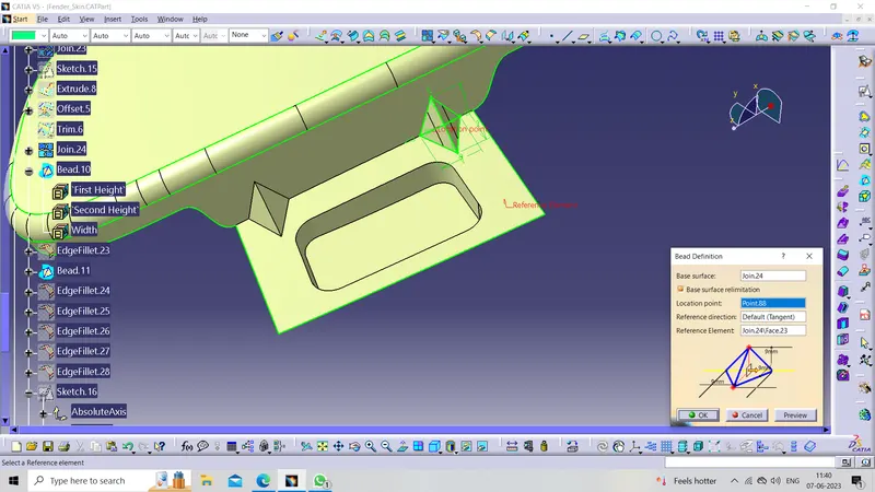
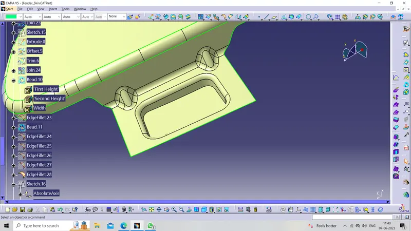
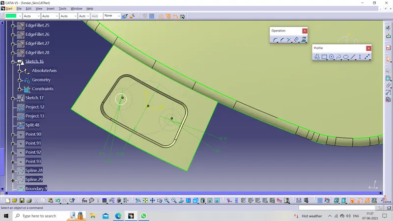
Now create Sketch for Holes And then project the sketch
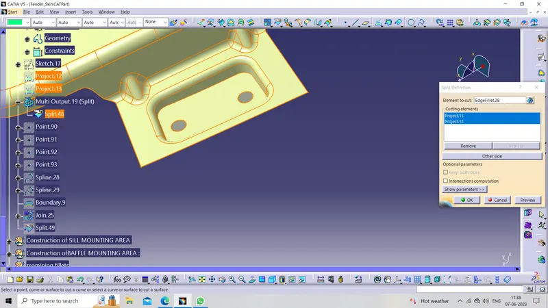
Now Split the above with the working surface
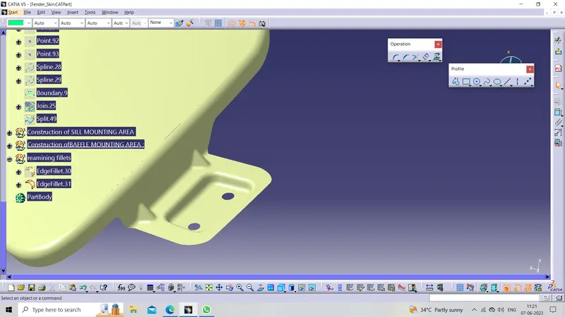
Now removing the sharp edges
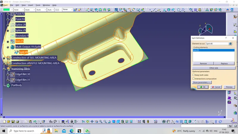
5. BAFFLE MOUNTING AREA :
In this region, the baffle gets installed to the fender with the help of clips that holds the baffle with the fender along the wheel arch.
For creating the Baffle mounting we create holes in the flanges of the baffle surface. By using a pushpin we we mount the baffle on the fender that's why we provide only holes on the Baffle mounting Area
Sketches
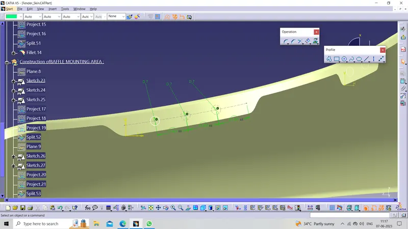
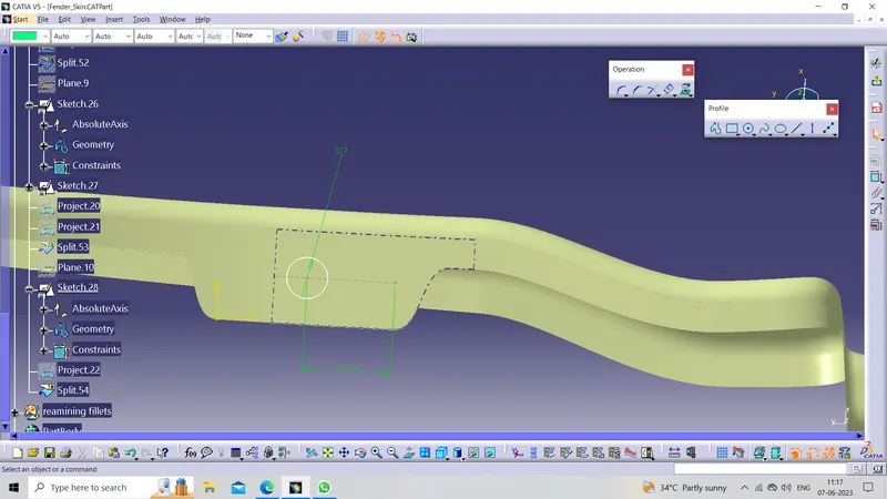
After completing the sketches Project the sketches by using the Projection 3d command And then Spilt the Working surface with the Projected sketches
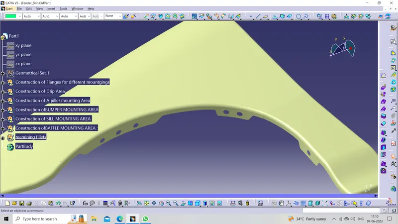
Here are some pictures of the designed fender from different angles, below
Isometric view
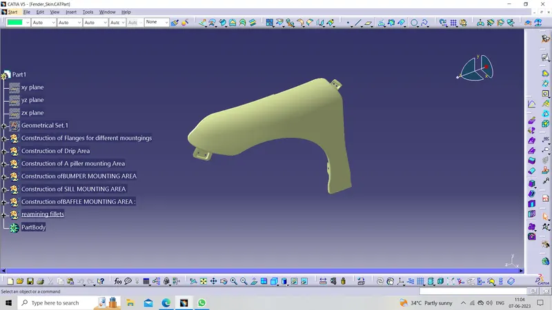
Rear view
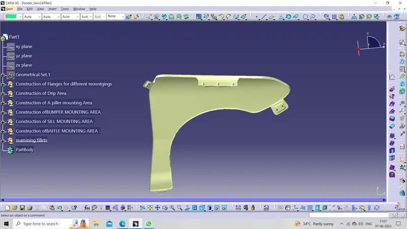
front view
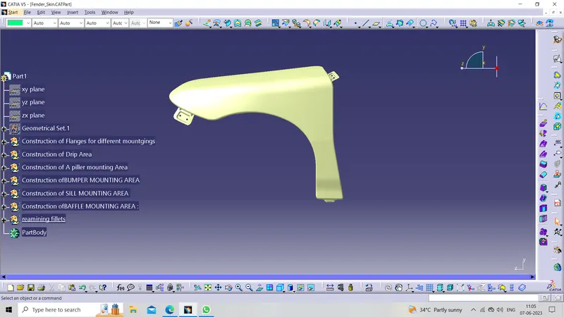
Side view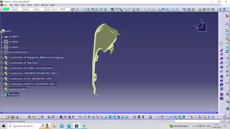
Top view
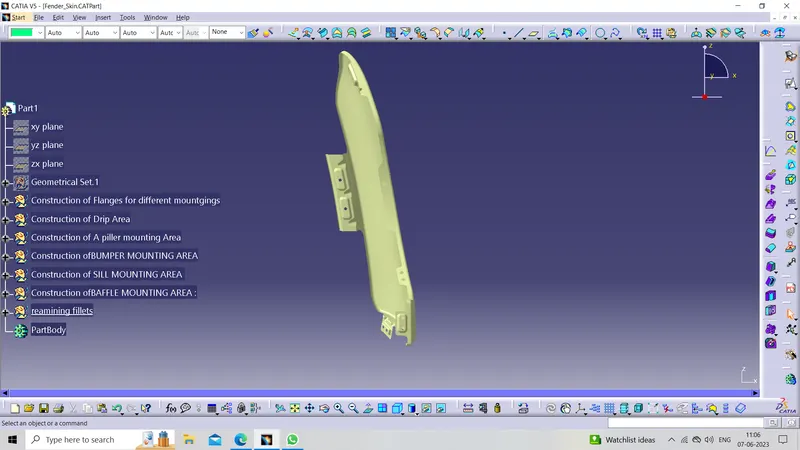
Manufacturing process:
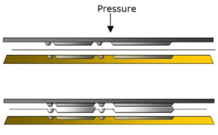
Embossing:
Embossing is the process of giving a 3-dimensional look to a material or product. Pressure is applied to the surface of the material and results in an image will project on the surface of the material. ‘Relief’ is another term used to encompass the process of embossing.
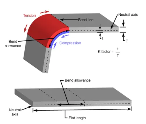
Bending:
It involves applying to the sheet metal workpiece to produce a curvature. In general, bending is used to produce a simple curvature surface instead of complex. The amount of pressure is important to change the sheet metal surface into the given shape.
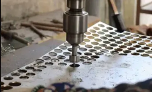
Drill:
Drilling a hole in sheet metal with a twist drill is a rather straightforward operation. You start by drilling a small diameter pilot hole and then drill gradually larger holes until you get to the size you need.
Conclusion:
Fender design is done using CATIA V5 software and the design has been created under the given parameters.