Fender Design
REPORT.
AIM: Design a front fender from the given skin data and the master section provided with Drip mounting, A-pillar, Sill, Bumper and Baffle (splash) Mounts.
Objectives:So our aim is to create a fender from the given skin data for that first we have to know what is fender?
WHAT IS FENDER?
Fenders are exterior body panels positioned at the leading edges of your vehicle that protect and frame the wheel wells, as well as covering the frame and sides of the engine block. They also safeguard other drivers and pedestrians from being hurt by stones thrown up by front wheels.
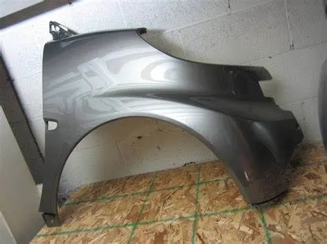
so basically there are two types of fenders are there:
- full bumper type fender
- half bumper type fender
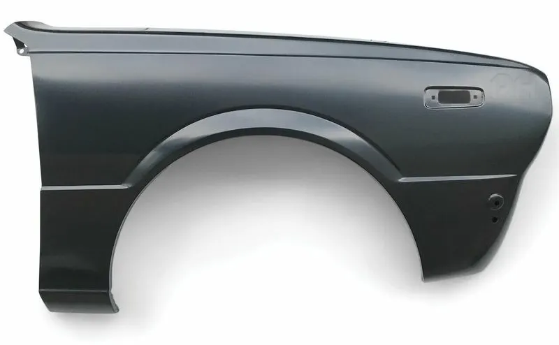
Full bumper type fender: The full bumper type fender was used in old cars it covers the full area until the front lighting. But it has a lot of sheet metal material which is unnecessary and increases the weight of the fender. These type fenders are no longer used in the automobiles.And it also reduses the performence of the vehicle.
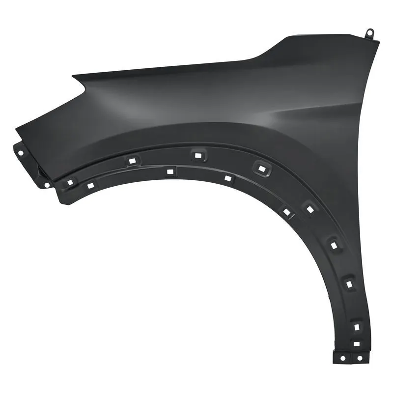
Half bumper type fender: Half-bumper type fender is popular and used when the headlamp casing is independent and housed between the bumper and fender. Moreover, the half-bumper type fender helps reduce material waste (scrap) while manufacturing as two fenders can be produced in a single blanking.
a fender is a automotive part which is connected to 5 different parts:
1.drip mounting
2.sill mounting
3.bumper mounting
4.A pillar mounting
5.Baffle or splash mounting
as per the design we have to create these 5 mounting as per the master section.
but before going to design let us know what is drip area mounting?
Drip area mounting is the part which connects the fender with the engine compartment. We use fasteners for joining the component.
sill mounting:sill mounting is the part which connects the fender with the sill.
Bumper mounting: bumper mounting is the area which connects the the bumper with the fender
A pillar mounting: A pillar mounting is the area which connects the A pillar with the fender
Baffle or splash mounting: Baffle or splash mounting is the area which connets the baffle plastic part with the fender.
so coming to fender design.
Fender is also a critical part in automotive. before designing a fender we have to calculate the wheel arch area as per the country regulations whether it is passing the regulation or not and then we have to start designing the fender.
so first we will recieve the class A surface of the fender along with the first flange as an input:
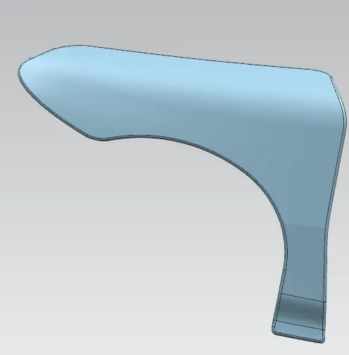
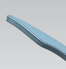
from this class A we have to create 5 different mountings as per the master section
but before creating the mountings first we will know descide our mountings are going to be positioned.by looking the fender we have came to know that our where our mounting are going to be positioned.
The master section we have is only for the drip area mounting so the rest of the mountings we have to decide where it is going to be. so for creating the drip reminding we want the extreme ends of the fender for getting the extreme ends first first we will create the a pillar mounting So for creating a pillar mounting by looking at the fender we can easily choose the location of the A pillar mounting and and then we will use offfset on face for 5mm because we are going to remove material and then we will create the curve on surface as per follows:
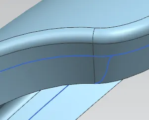
after getting the curve on surface we will take a datum plane from the other end with a offset value of 150 mm because the head light has to assemble there so we will leav e a gap of 150 mm and then we will take a another datum plane on the egde of the curve on surface with a offset value of 150 mm because the engine has to assemble there with a offset value of 150 mm as per the master section it is 200 mm or we can take less also so i have taken 150 mm and then we will take a intersection curve on the both plane and then we will take offset curve on surface and create a tangent cuve and then we will trim the extra portins and then our output will be as follows:
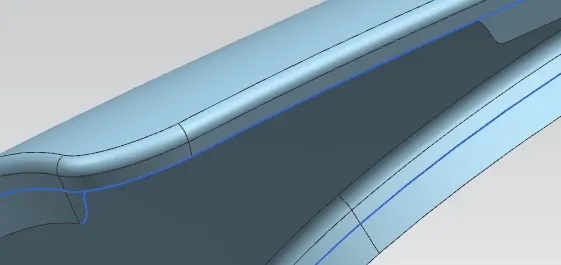
like this we will choose the locations of the other mounting and then we will create tangent curve on surface and then we will trim the extra portions and then we will recieve the output as folows:
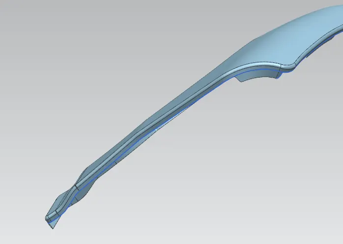
after trimming the extra portions we will work on our drip are mounting. the flange which is already there is too long so we will trim it aliitlt bit and then we will work on.
first we will create the slant surface which is at 40 degree from horizontal and 8 mm length so we will use law extension and create it.
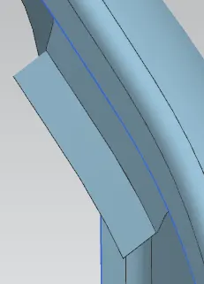
after getting this we have to create a vertical flangewhich is 5 degree from vertical and the height is not given so we have to assume the height of the vertical flange so here also we will use the law extension and we will give the height as approx and then we will check the total height if the height is more than 40 mm it is not accepted because we will have spring back effect so as per the master section it should be 40 mm or less than 40 mm keeping this thing in mind we will give the height and we will recieve the output as follows:
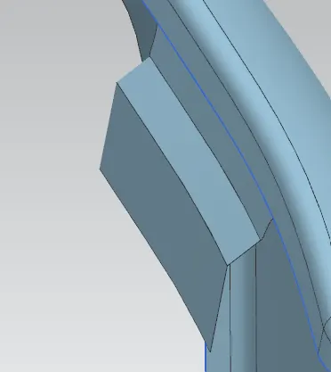
after getting this we have to create the vertical falnge which is 25 mm length and the angle is not given so we will assume it as 0degree and we will recieve the outp[ut as follows:
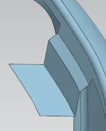
after getting these we have to create the rest three flanges for that we the height and the angel and the totla length is given but not the individual length is given so we will use some trignometric functions and calculate them and then we will use law extension and we will recieve the output as follows:
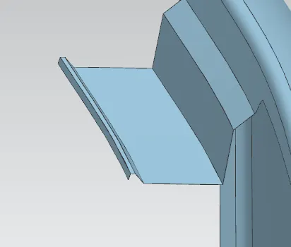
after creating all the flanges we will make them as a single component for making it as a single component we will sew them all and after that we will create a datum plane on horizontal flange with a offset distance of 3 mm and then we will start creating the emboss.
for creating the emboss we will use the new plane which we created and do the sketch and then we will project the sketch and the we will use the emboss command to create the emboss.
why we have used the datum plane on the horizontal surface means the fender is going to mount on the engine compartment and the it will be locked with the fastners the fastners want a flat surfacebut the horizontal surface is not flat so we created a datum plane in that particular area.
after creating the emboss we will create the holes on the emboss for the fastners and then we will give the blends and then our output will be as follows:
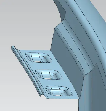
after creating the embosses the vertical and horizontal surface needs to be have something to strengthen for that we will use dart and then we will give blends for them also and we will recieve an output as follows:
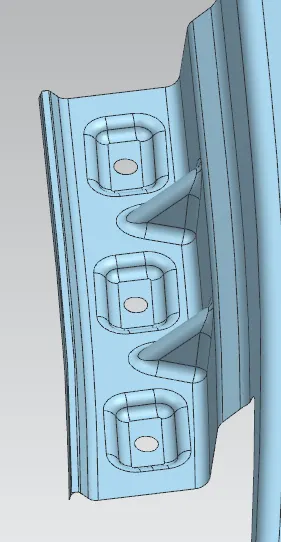
once if we done upto here our drip area mounting is done.
now we will look on bumper area mounting. for the bumper area mounting we have keep the required portions and trimmed the unwanted portions.we have done the same procedure which we followed for the drip mounting to cut the material we have used the curve on surface to get a tangent curve surface .
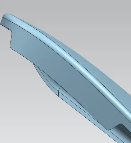
after getting the bumper are mounting surface we will use law extension on the edge of the mount and we will recieve an out put as follows:
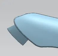
since we do not have any master section for the bumoer mount we have assume all the values so i have assumed the length of law extension as 40 mm.
after doing law extension we have to create a three point datum plane on the law extension with a offset value of 3 mm to get get a flat surface for emboss we are using the datum plane.
after creating the datum plane we have to create the sketch on that plane and then project the sketch of emboos and fasteners hole and then use emboss command to get the emboss and then trim the sheet to cut the fastners hole and then we have to give blends the vlaue will minimum 3+thickness of the component and then we will recieve the output as follows:
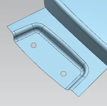
after getting the embossed surface we will sew them with the main surface and then we will give dart for both the surface to make the both surface stronger and then we will give blend for them also and we will recirve the output as follows:
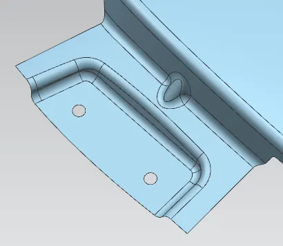
once if we done upto this much our bumper mount is also ready.
after getting the bumper mount and the drip area mount we will create the mounting areas for the baffle or splash area. for creating the mount for baffle area we have already trimmed the unwanted portions so we have our surface as follows:
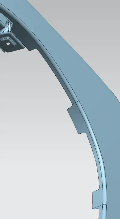
we have the surface in 3 areas why because the babaffle is going to come around all the three palces and more over the baffle is a plastic part so we dont need to create the emboss we can directly create the holes because on the baffle we dont use fastners instead of fastners we will use pushpins.
for creating the holes for push pins we will create a direct plane on the required surface and then we will create the sketch for push pin hole and then we will project the sketch on the surface and then we will trim the sheet and we will recieve the output as follows:
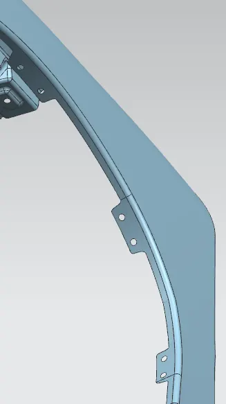
once if we get the hole our baffle mount is also done.
after creating the three mounts we will create the sill area mount.
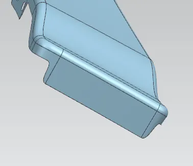
For creating the sill area mount we will first extend the sheet of our surface why because our fender is going to assemble on the parallel so it does not need any law extension so we will extend the sheet of the required surface and then we will create a three dot plane with a offset value of 3 mm and we will recieve the out put as follows:
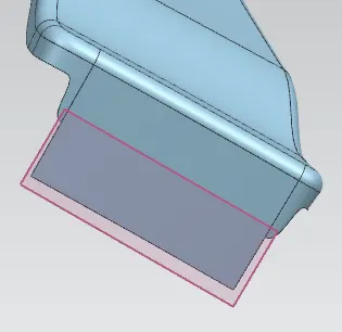
after getting the plane we will do the emboss sketch on the palne and then we will project the sketch on the surface and then we will use emboss command to create emboss and then we will create the fastners hole using the same plane and then we will teim the sheet and we will recieve the output as follows:
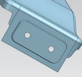
after getting the emboss and the fastners hole we will give blend the blend value will be 3+thickness of the component that is the thickkness of our component is 0.75 mm so the blend vlaue will be 3.75 mm.and then we will recieve the output as follows:
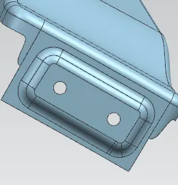
once upto this much is done then our sill mounting is also done then we have to focus only on the A pillar mounting.
for A pillar mounting we have the trimmed surface as following image:
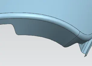
so for A pillar mounting we will use law extension on face method and we will recieve the output as follows:
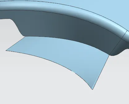
since ther are no master section is given we have assume the length of the law extension as per our requirement and if we look carefully on the law extension we are having a bad surface so we dont want bad surface so we will use curve on surface and create a cure which is not laying on the bad surface and then we will trim the sheet using that curve and we will recieve the output as follows:
BEFORE TRIMMING:
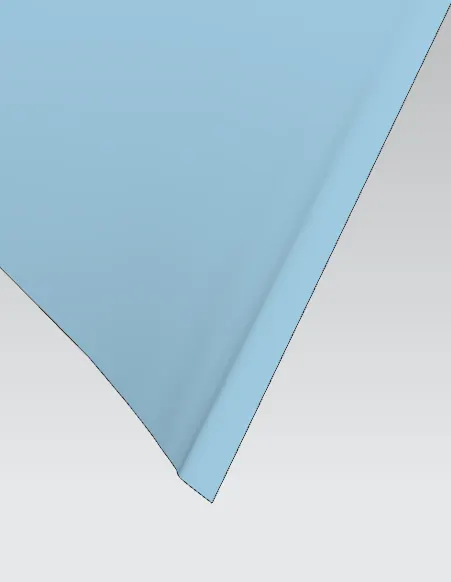
AFTER TRIMMING:

after trimming the bad surface we will create the emboss and the fastners hole for that we will create a three point datum palne with a offfset value of 3 mm and the we ill do the sketch and then we ill project the sketch on that surface and then we will use emboss command and then we will trim the sheet with the holes to and then we will give blend and we will recieve the output as follows:
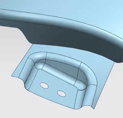
after creating the emboss we will sew the embossed surface with the main surface and then we will create a dart to strength both material and then we will give blend and then we will recieve the output as follows:
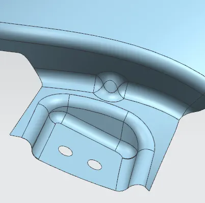
once if these is done then all the mounting are done but we should not have any sharp edges to remove the sharp edges we will use bridge curve on all the sharp edges and trim the sheet and we will recieve the output as follows:
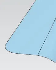
like the above image we have to remove all the sharp cornes.
once if this all done then we have thicken our fender for 0.75 mm and we will recieve the output as follows:
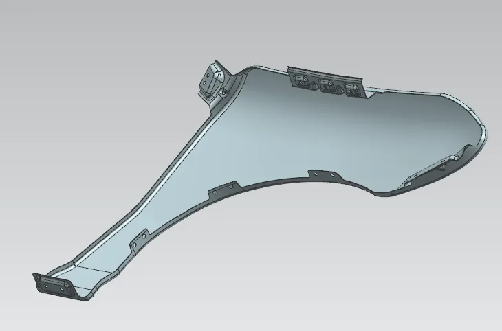
once if we get the thickened component our fender is ready.
MANUFACTURING PROCESS OF THE FENDER:
A car Fender bumper is made by a process called reaction injection molding (RIM), which basically consists of making a special polyurethane compound and introducing it into a large fender. RIM is a process that conserves raw materials and reduces costs.
car fenders are made up of plastic, steel, aluminum, and modern plastic composites like thermoplastic and fiberglass. Usually, heavy vehicles like trucks, utility vehicles, and SUVs are equipped with metal or steel fenders, whereas passenger vehicles have plastic fenders.
DESIGN PARAMETERS OF FENDER:
Height of fender can be minimum 80mm for child and adult 94mm,WAD 1700MAX, this +14 for increase in inertial force due to accident impact. Parting will minimum 5 not more than 50mm from SRL a reference line on HOOD side, a point on fender makes from a line of 45 degree from ground level .