Fender Design
AIM : From the given CLASS A SURFACE of the FENDER we have to made changes in the design and develop the model with some extra features that are :
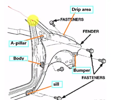
Mounting Area:
- Bumper
- Drip
- A Pillar
- Sill
- Baffel
Introduction:
Fender:
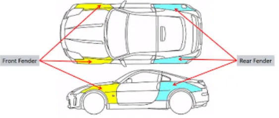
Fender is a part of the vehicle that frames the wheel . The primary purpose of the fender is to prevent sand , mud , rock etc from being thrown away into the air by rotating tire and harm pedestrians.
There is two types of fender in a car body, front fender and rear fender as shown
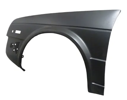
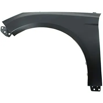
Fender can be of two types , full bumper type and half bumper type . Nowadays half bumper type fender is typically used . the cost of sheet metal blank is reduced as we can produce two half bumper type fender in single blank . This also leads to reduction of scrap.
FULL BUMPER:
HALF BUMPER:
DESIGN FEATURES OF FENDER:
Mounting Area:
- Bumper
- Drip
- A Pillar
- Sill
- Baffel
Bumper:
The bumper mounting area is used to fix the plastic bumper to the fender with the help of the fasteners
Drip:
- It is the important mounting uni of the fender . it is connected with the engine compartment, therefore a lot of design constraints are to be followed while designing the fender
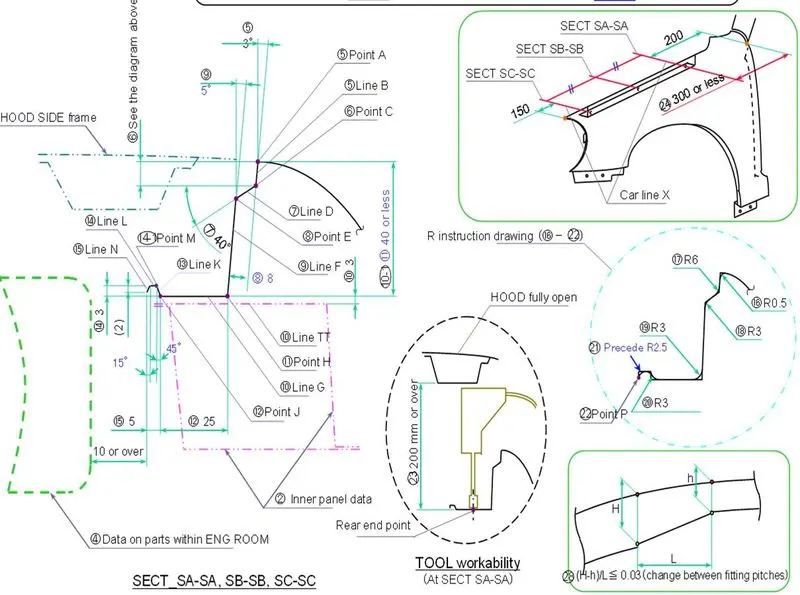
- While designing the drip area we have to initially leave 200-300 mm for the cowl top
- For placing the headlamp we have to leave at least 150 mm at the front while designing the fender
- The cowl top part consists of a wiper motor and its instruments
Sill:
The sill is the panel directly below the bottom of the door supporting the floor and may be used to combine the floor and the body. The bottom end of the fender is mounted on the sill body for reinforcement of the fender panel , thus the sill mounting position is designed with holes and emboss. M5 fasteners are used to fix the fenders on the sill body.
BAFFLE MOUNTINGS:
Baffle mounting or mudguard are clip-fit types of mounting on the inner side of the fender arch over the Tyre. it protects the car engine compartment and pedestrians from causing injuries from chip-out debris on the road when the car is in motion. they are mounted on the fender using a special type of locking clips which are made up of plastics.
A-PILLAR AREA:
The A-pillar is the structural pillar that combines the body with the roof . this makes the sides of the windshield rest . front fenders are fastened to the A-pillar to form a robust structure.
Manufacturing process The manufacturing of the fender majorly involves these operations.
L.Embossing
2.Bending
3.Cutting and Blanking
Embossing:
Embossing Embossing is a metal forming process for producing raised or sunken designs or relief in sheet material using matched male and female roller dies, theoretically with no change in metal thickness, or by passing sheet or a strip of metal between rolls of the desired pattern.
Bending:
Metal bending is a process by which metal can be deformed when applying force to the subject, which causes it to bend at an angle and form the anticipated shape, which often results in it being in a 'V' or a 'U' shape. This is done through the application of force on a workpiece. The force on the work piece can be mechanical, pneumatic or hydraulic
Cutting and Blanking :
Cutting processes are those in which a piece of sheet metal is separated by applying a great enough shearing force to cause the material to fail. Blanking is a steel manufacturing process in which a flat, geometric shape is created by feeding a coil of sheet metal into a press and die in this process, the blank is punched out from the large metal sheet.
MAIN CONSEDARARION
Drip Area :
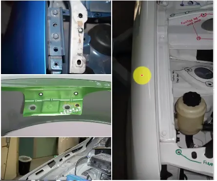
In out of 5 mounting points drip area is the very critical design.
Given master section of the DRIP AREA :
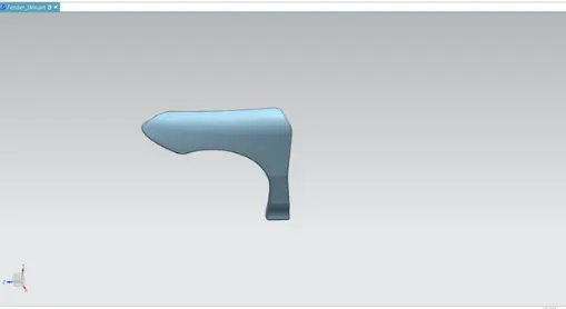
Input skin (Class A surface) :
Drip area Design:
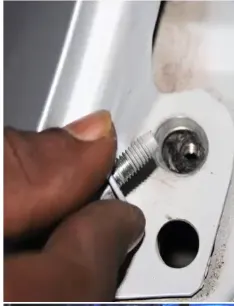
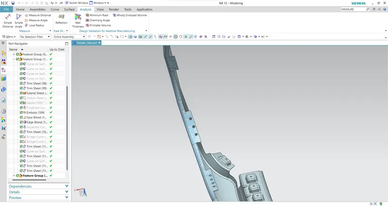
Drip area mounting is the important part in the fender . This mounting is attached to the engine compartment of the car . Fender drip area is mounted via weldnuts to the engine compartment.
- The height of drip area mounting should be less than 40mm so that it reduces the springback effect during manufacturing and reduce NVH issues during vehicle movement.
- Mounting screw holes of dia 5mm are and locator pin holes are created for mounting guidance.
- It should be distanced atleast 150mm from the front side ande 200m from the rear side .
- Ribs are to be provided in order to increase the strength of the mounting part .
- Embosses are created as per design standards for proper fixation.
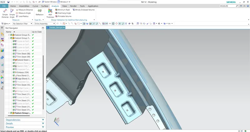
A-pillar design:
The A-pillar area mounting depends upon the A-pillar of the car .
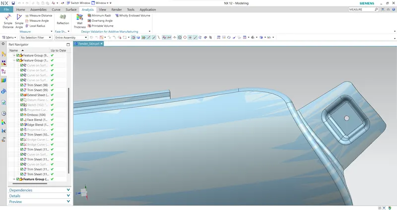
Bumper area Design:
This is designed by consulting the bumper design team to design the bumper and fender assembly fixation.
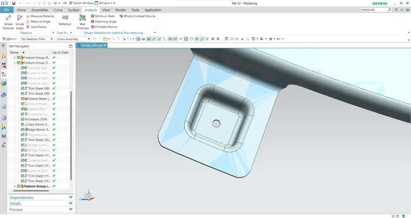
Sill area mounting Design:
Sill area mounting is also an important mounting part .This mounting point is basically on the bottom of the fender . The mounting part should be created such that the fender is firmly attached to the sill to avoid NVH issues.
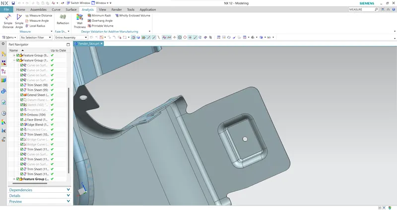
Baffle Mounting area Design:
Result:
A thickness of 0.75mm is given to the surface to produce solid body
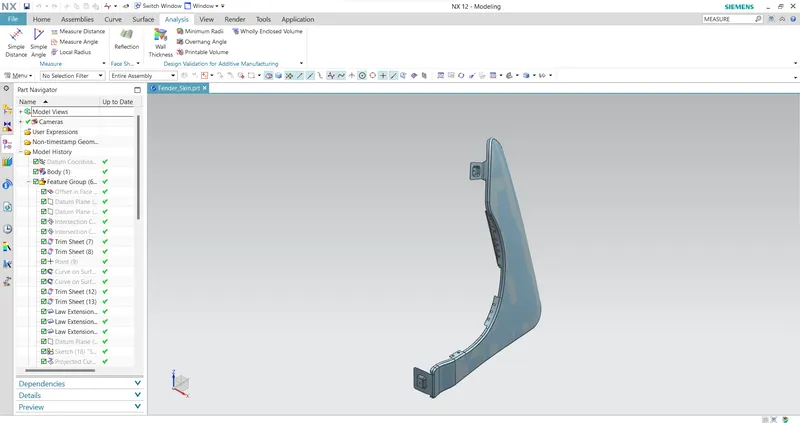
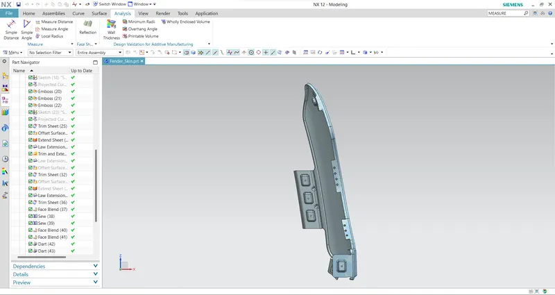
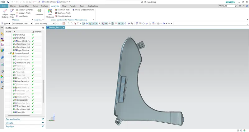
DIFFERENT VIEWS:
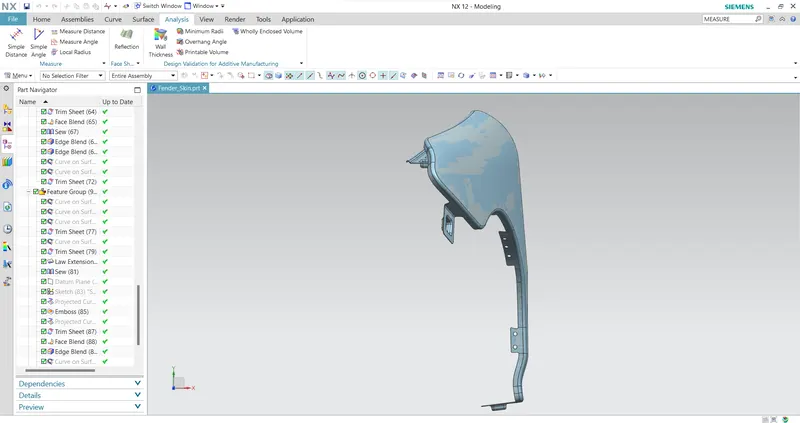
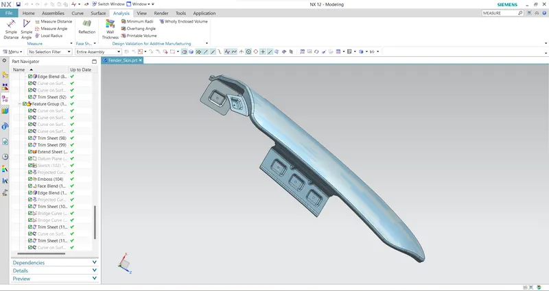
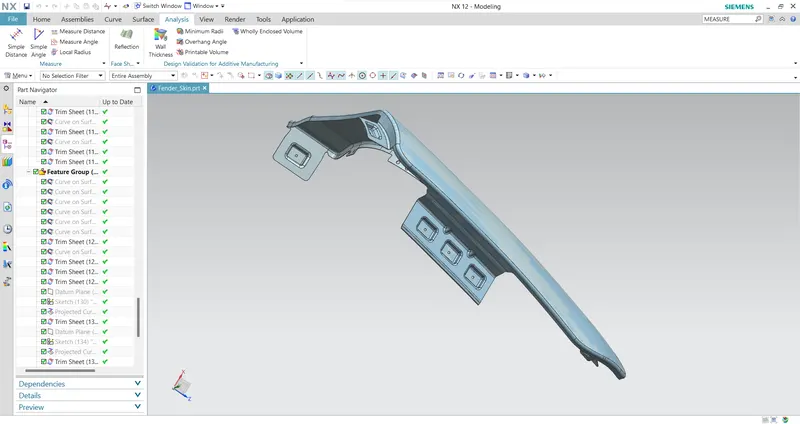
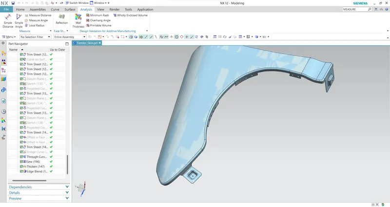
Commands used from NX CAD to model this fender are:
- Offset in face
- Curve on surface
- Trim sheet
- Law extension
- Datum plane
- Intersection curves
- Face blend
- Bridge curve
- Sketch
- Projected curve
- Emboss
- Edge blend
- Sew
- Dart
- Thicken
Conclusion:
The fender of the automobile is checked for the wheel arch radius as per Europen regulations and designed the front half fender of a car using master section and by following the pedestrian's safety and in order to guard the engine compartment and beside the vehicle.