Fender Design
Fender:
Fender is a part of the vehicle that frames outer cover of the wheel . The primary purpose of the fender is to prevent sand , mud , rock etc from being thrown into the engine compartment and the inner part of vehicle during rotating tire.
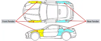
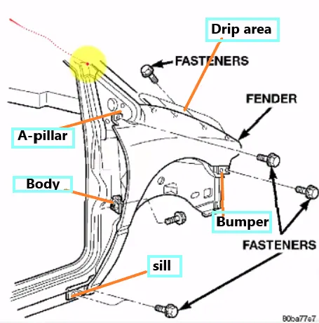
The major design features of the fender are:
- Bumper
- Drip
- A Pillar
- Sillt
- Baffel
TYPES OF BUMPER
Full bumper
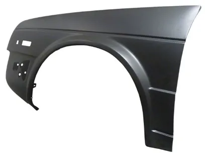
Half bumper
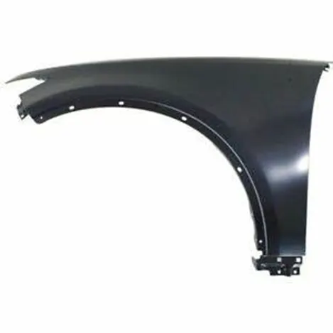
In recent days, the vehicles are almost mounted with the half bumper.
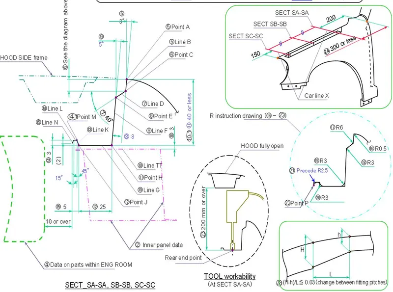
The master section of the drip area is given below:
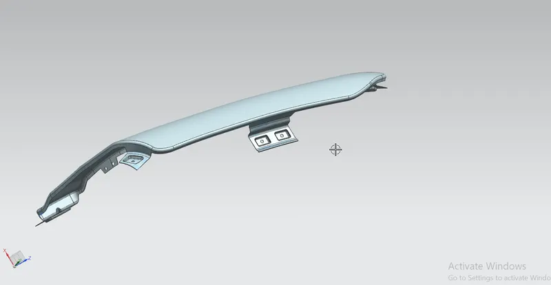
Drip area Design
Drip area mounting is the important part in the fender design. This mounting is attached to the engine compartment of the vehicle . This area is mounted by using the fasteners. The height of drip area mounting should be less than 40mm. This is based on several experiments so as to reduce the springback effect during manufacturing and reduce NVH issues during vehicle movement. Mounting screw holes of dia 5mm are and locator pin holes are created for mounting the fender. The distance should be atleast 150mm from the front side and 200m from the rear side .Ribs are to be provided in order to increase the strength of the mounting part. Embosses are created as per design standards and it is drafted and filleted for proper fixation.
A-pillar design
The A-pillar design and its mounting doesnot have a proper standards as it varies depends upon the A-pillar of the car .
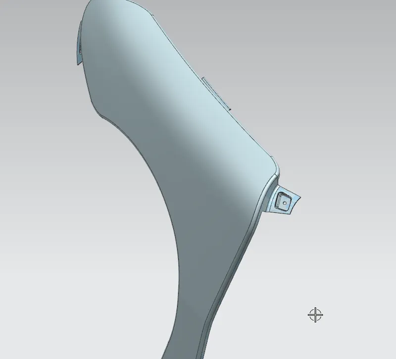
Bumper area Design
This is designed according to the design of the bumper and fender assembly fixation. This also varies from vehicle to vehicle.
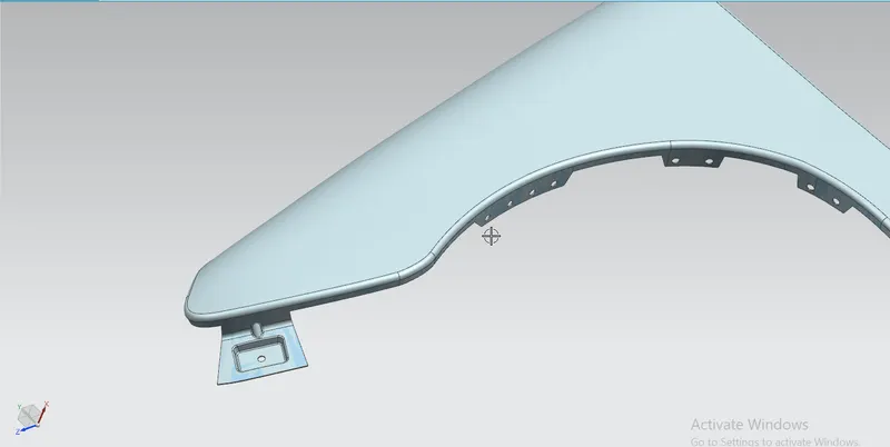
Sill area mounting Design
Sill area mounting is located on the bottom of the fender. The mounting part should be created such that the fender is firmly attached to the sill to avoid NVH issues.
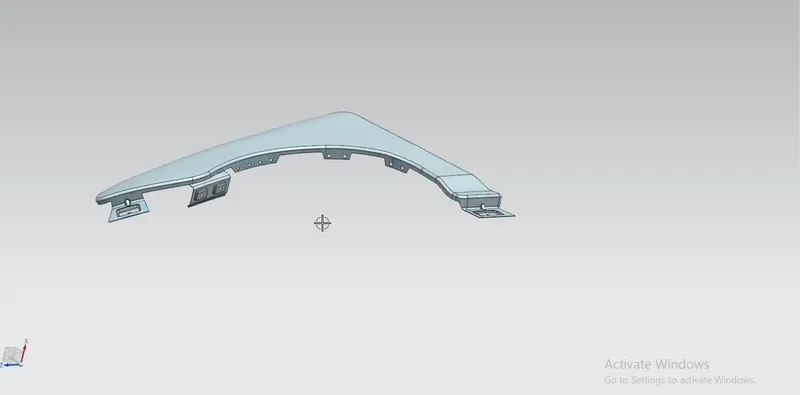
Commands used from NX CAD to model this fender are:
- Offset in face
- Curve on surface
- Trim sheet
- Law extension
- Datum plane
- Intersection curves
- Face blend
- Bridge curve
- Sketch
- Projected curve
- Emboss
- Edge blend
- Sew
- Dart
- Thicken