Fender Design
AIM : To create the Drip Area by following the given Master section and to create our own design for the Sill, Bumper, Baffle(Splash), and A-Pillar mounting according to the Engineering standards that you learned.
FENDER :
Fender is the US English term for the part of an automobile (vehicle body) that frames a wheel well (the Fender underside ) .
- Its Primary purpose is to Prevent Sand ,Mud , Rocks, Liquids and other road spray from being thrown into the air by the rotating tire .
- When vehicle is moving, tyres pick up stones and others and hurl them in all directions. Fenders are basically present to prevent any injuries to pedestrians and contain the motion of these particles
- Most passenger automobiles have four fenders, one over each wheel. For vehicles with a narrow car body that exposes the tire, the fender is an exposed curve over the top of the tire. For wide body vehicles that cover the tire, the fender forms the wheel well surrounding the tire, and is not directly visible from above the car body.
- Wheel wells tend to be much larger than the diameter of the tire, because they do not move with the tire suspension and consequently must be large enough to allow the full range of tire motion on the suspension without touching the interior of the wheel well.
- More elaborate designs include fender kirts for enclosing the outside edge of the wheel well, and stylized pontoon fenders for exposed fenders.
Types of Fenders:
They are two types of Fenders
- Full Bumper type .
- Half Bumper type .
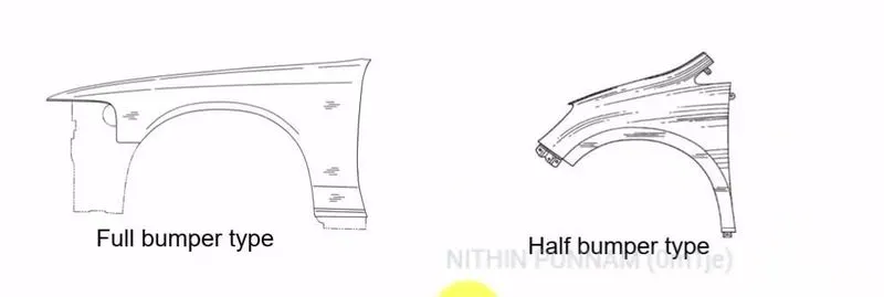
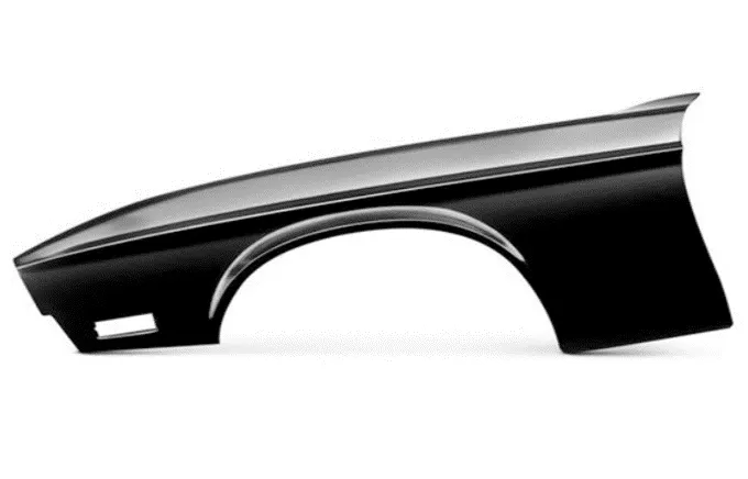
Full Bumper type :
- This style of bumper was present on earlier models of vehicles but is not currently manufactured. It will cover the area from the side door to the car's headlight.
- The manufacturing process has created more wastage and consumes raw Material so that development and production reduce in the modern period.
Half Bumper type :
- This type of bumper is used in modern day because of the reduced raw material wastage, reduction in car weight to improve performance and manufacturing cost is low compared to full bumper type.
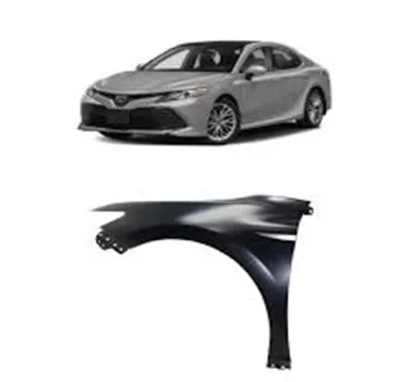
Mounting
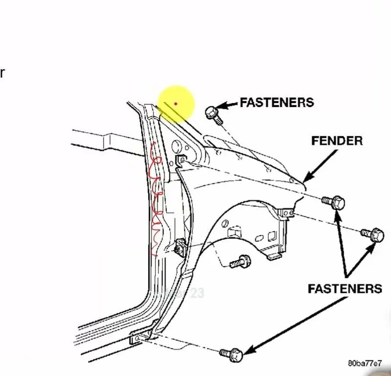
There are 5 Mounting points in a Fender .They are :
- Body or Bumper
- A Pillar
- Sill
- Cowl or Baffle plate mount
- Drip Area
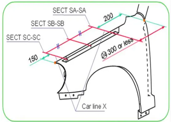
Design Data Parameters :
Individual Design of Parts :
- Creation of Drip area section
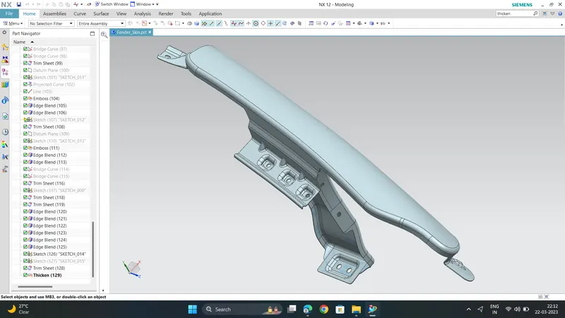
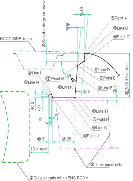
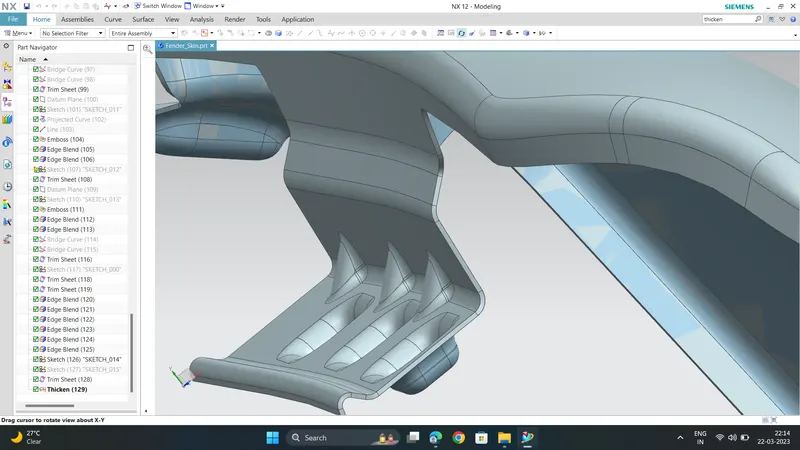
First create the flanges according to the master section providded ,in the drip area using " Law extension " command and then draw sketches to create " emboss " and give suitable " face blends " or " edge blends " wherever required to avoid sharp corners
Here , To create Dart between the faces , First we need to join the two faces where we want to create dart using " Sew " command . Then , go to the " Dart Legacy " command select one face first and then click on second face and adjust the parameters available like Height and Depth to get desired output .
Also create Hole cut-out there . so to create it , first draw circle and use " Trim sheet " command .
Hood side Drip depth must be 40mm or less as maximum productivity is achieved at the length of 40mm . If depth exceeds 40mm ,rigidity bead is to be provided . Also, Forming operation is not feasible if
depth exceeds 60mm due to Wrinkling and Springback effect .
When the Drip surface is Stamped , 3 degrees must be secured for springback .
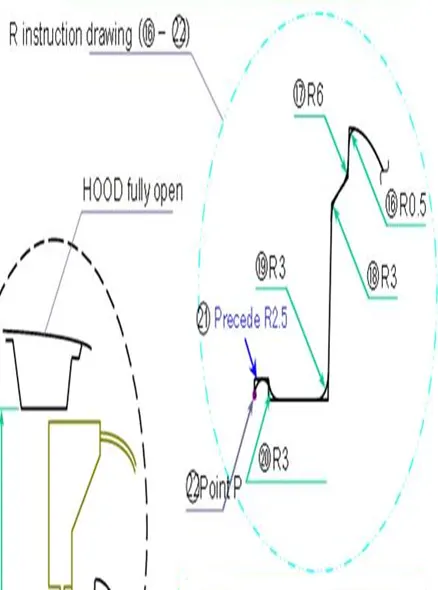
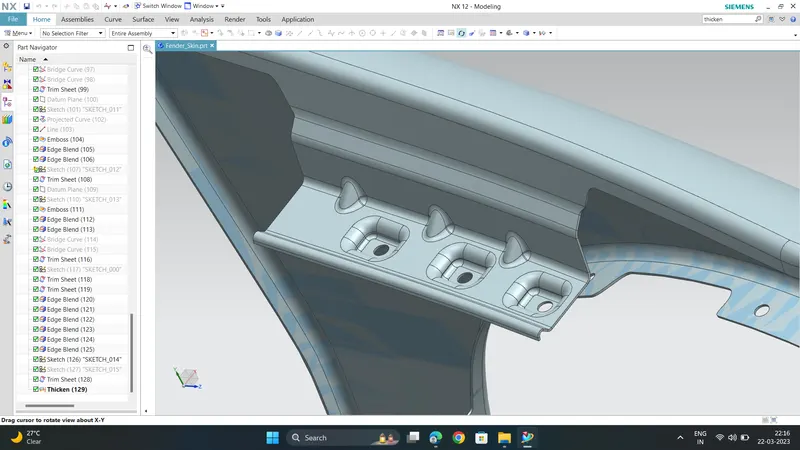
The drip area uses to mount fender near the engine part with at least 10mm and above clearance is necessary.
Make sure that to give sufficient space for cowl mount.
2. Creation of Bumper Mount
This Mount is used to connect the Fender and the Bumper of car.
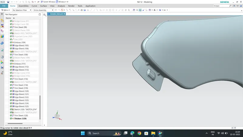
First create a surface and then create " emboss " and if required Dart . Then give face blends or edge blends to avoid sharp corners
3. Creation of Sill Mount
The region is mount on sill Which is the bottom area of the fender .
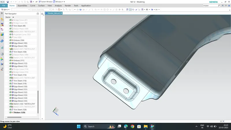
here , create " emboss " and the Hole cut-outs on the surface created .
4. Creation of Baffle Plates Mount
It is used to prevent engine comportment from stone chips, mug hitting on it .
It is Mounted on the plastic material.
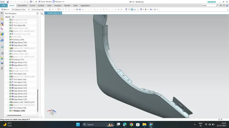
First create 3 flange type structures there and then create Hole cut-out using " Trim sheet " command . Also provide " Relief " if necessary .
5 . Creation of A Pillar Mount
This is used to connect A-pillar Section and Fender.
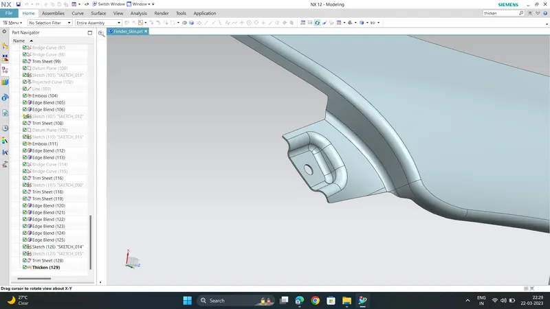
First create the " emboss " on surface and then create Hole cut-out . Also give edge blends of minimum 3.75mm .
Final Design of Fender :
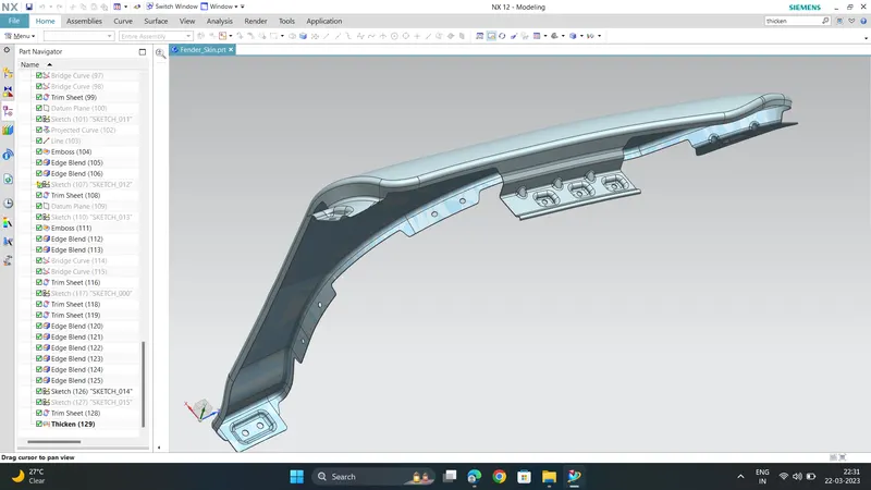
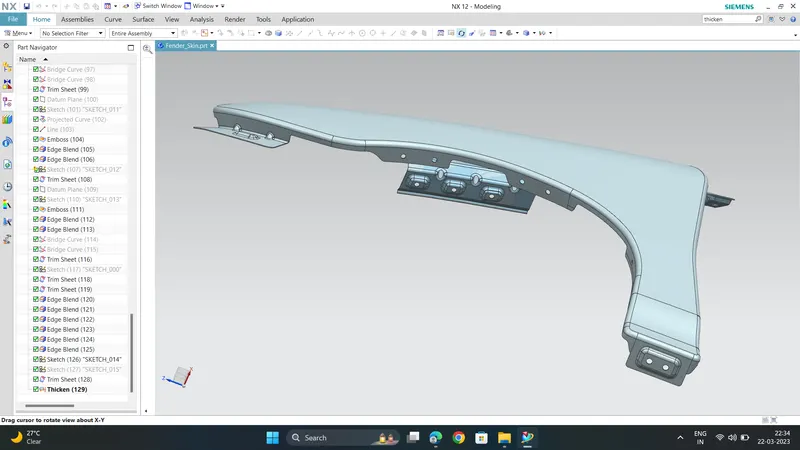
After creation of all Mount Points on a fender , thicken it using " Thicken " command .
Manufacturing process :
Generally ,the process of deformation begins with a blank, a quantity of metal in some basic form that will undergo the change in shape. The blank becomes the workpiece -the piece of metal to be reshaped in the metal forming process. For automotive metal forming, the blank is often made of sheet metal, which can be stamped, cut or bent into a shape needed for an automobile's body.
Here are the some ways that a metal workpiece can be deformed during the automotive manufacturing process:
1) Stamping :
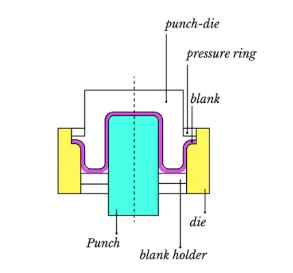
In stamping, a device called a Stamping Press is used with a series of dies to cut and form metal into various shapes. This is commonly used to make automotive parts such as hubcaps and fenders
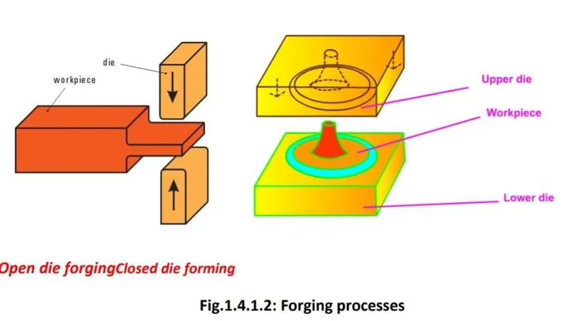
2) Forging:
Forging is a bulk forming process in which the work piece or billet is shaped into finished
part by the application of compressive and tensile forces with the help of a pair of tools
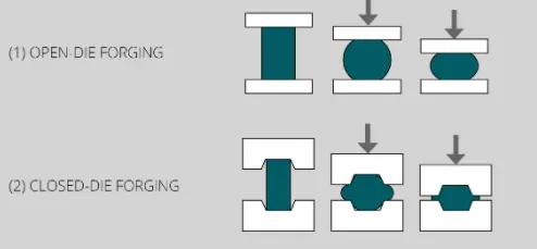
called die and punch. Forging can be done in open dies or closed dies.
Open die forging is usually used for preliminary shaping of raw materials into a form suitable for
subsequent forming or machining.Open die forming is done using a pair of flat faced dies for operations such as drawing
out, thinning, etc...
Closed die forming is performed by squeezing the raw material called billet inside the
cavity formed between a pair of shaped dies. Formed products attain the shape of the
die cavity. Valve parts, pump parts, small gears, connecting rods, spanners, etc are
produced by closed die forming.
The forging process uses a hammer or press that is essentially a mechanized version of the hammers used by ancient blacksmiths. The metal is hammered against a surface that serves as an anvil. It can be hammered repeatedly so as to form complex shapes. This can be used as an alternative to the drawing process.
3) Extrusion:
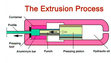
Extrusion involves forcing the raw material through a narrow opening of constant cross-
section or varying cross-section in order to reduce the diameter and increase the length.
Extrusion can be done hot or cold. Extruded products include shafts, tubes, cans, cups,
gears.
Basically there are two methods of extrusion, forward and backward extrusions. In
forward extrusion the work and the extrusion punch move along the same direction. In
backward extrusion the punch moves opposite to the direction of movement of the
work piece.
Extrusion can be used to produce long metal objects, such as rods and tubes. The metal workpiece is forced into a die with a hole in the opposite end. The metal is extruded through the hole to form the shape. Extrusion can be used to manufacture important parts of a car's drive train or the anchors that hold seatbelts in place.
4) Drawing:
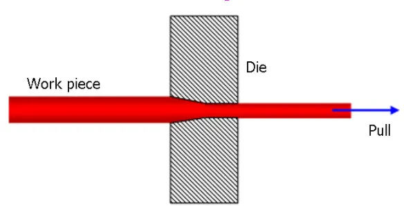
In drawing, the sheet metal is forced against a die that has been cut into the three-dimensional, often curved shape that the sheet metal is to take on. In effect, the die is used as a mold for the metal. This technique can produce relatively complex shapes. Once again, pressure is applied to the workpiece using a hydraulically or mechanically operated punch. There are a number of dangers involved, not so much to people (since the process is largely mechanized) but to the metal itself. It can crack from too much pressure or wrinkle from its interaction with the die. Lubricant can be used to make the metal slide more smoothly against the die, avoiding the possibility of wrinkling. Alternatively, the wrinkled edges can be trimmed from the metal in a separate operation. This method is commonly used to make auto body parts and fuel tanks.
Embossing:
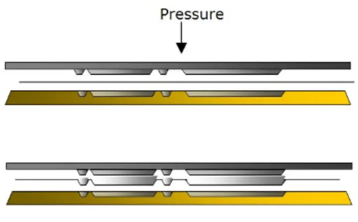
Embossing is the process of giving a 3-dimensional look to a material or product. Pressure is applied to the surface of the material and results in an image will project on the surface of the material. ‘Relief’ is another term used to encompass the process of embossing.
Bending:
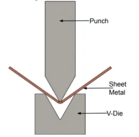
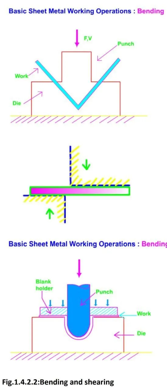
In bending, force is applied to a sheet metal workpiece to produce a curvature of the surface. Bending is generally used to produce simple curved surfaces rather than complex ones. A mechanically operated press drives a punch against sheet metal, forcing it into a simple die with enough pressure to produce a permanent change in the metal's shape. The amount of pressure is important. If not enough pressure is applied, the metal can simply spring back into its original shape. If too much is applied, it can break.