Fender Design
Hi,
Here I am submitting the Fender design & other reinforcements.
- First, I have started with offsetting the outer most edge of the fender skin to 5mm using ‘offset in face’ tool.
- Using ‘curve on surface’ tool created tangent edges to the offsetted curve and the outermost curve, where wanted & trimmed that all using ‘trim sheet’.
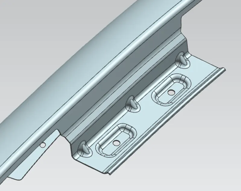
Procedure followed for Drip area design:
- First, I have offsetted the edge to 0mm & created a datum plane of 150mm at a side & a same at either side.
- Then created the intersection curve using the planes on the surface by using ‘Intersection curves’ tool & made sure that the 200mm & 150mm offset on either side.
- Using ‘Law extension’ created a flange for the drip area of 8mm at 40 degrees.
- Again used ‘Law extension’ of 8mm & at 5 degrees downwards from the previous flange.
- Again used ‘Law extension’ of 25mm & at 0 degrees perpendicular to the previous flange for the drip mounting.
- Again used ‘Law extension’ of 4.24mm & at 45 degrees from the previous flange.
- Again used ‘Law extension’ of 1.5mm & at 0 degrees downwards from the previous flange.
- Again used ‘Law extension’ of 2mm & at 15 degrees downwards to the previous flange.
- Then I have sewed the flanges to apply dart.
- Then drawn a sketch of a rectangle 25 x 11mm & made the edges filleted of 4mm radius.
- And drawn a circle on the centre of the rectangle of diameter 10.
- Then projected the sketch on the drip area mounting surface.
- And created embosses of 3.5 depth at 15 degrees.
- And using ‘trim sheet’ trimmed of the circle drawn.
- Then used ‘edge blend’ on the edges to make smoothen surface.
- Then applied dart on the mounting flange to strengthen the flange of 5mm depth & 2mm radius at both the ends & at the mid of the flange.
- Thus, finished the drip area design.
Procedure followed for Fender sill mounting design:
- By trimming the outermost edge of the fender by offsetting the edge & trimmed it already.
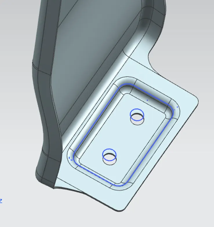
- I have started with ‘curve on surface’ to trim the sharp corners.
- And extended the flange using ‘extend sheet’ to 15mm.
- Then created a datum plane tangent to the flange & drawn a rectangle of 40x22.5mm & filleted the edges to 4mm.
- And drawn the mounting holes of diameter 10 x2 symmetrically on each half side of the rectangle.
- Then created the emboss on the flange of 3.5mm depth at an angle of 10 degrees.
- Then trimmed the mounting holes using ‘trim sheet’.
- And filleted the edges of the emboss using ‘face blend’.
- Then using ‘bridge curve’ filleted the edges of the flange.
- Thus finished the Fender sill mounting design.
Procedure followed for Fender A-pillar mounting design:
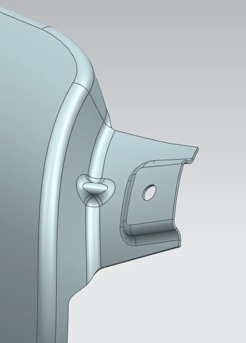
- First, I have started with law-extension of 35mm at the edge & at an angle of 90 degrees on the A-pillar side.
- Then, used ‘curve on surface’ on the law extension edges on both sides.
- And trimmed off those using ‘trim-sheet’ to cut off non blended surfaces.
- Then created a datum plane tangent to the surface created.
- And created a rectangle of 25 x 25mm & a circle on the centre for screw mounting of 3 diameter.
- Then using ‘projected curve’ projected those on the surface.
- Then using ‘law extension, extended the edge perpendicular to the surface of 3.5mm & at 75 degrees.
- Then offsetted the previous law extended surface to 3.5mm.
- Then trimmed off the external surfaces to the surfaces created to create the emboss using ‘trim sheet’
- Then blended the embossed surfaces using face blend.
- Then trimmed off the mounting hole of 3.5mm.
- Then used ‘dart’ to create a rib at the mid of the arc length of 5mm depth.
- Then blended the flange edge to 3mm using ‘edge blend’.
- Also filleted the dart edges.
- Thus finished the A-pillar mounting design.
Procedure followed for Fender body side mounting design:
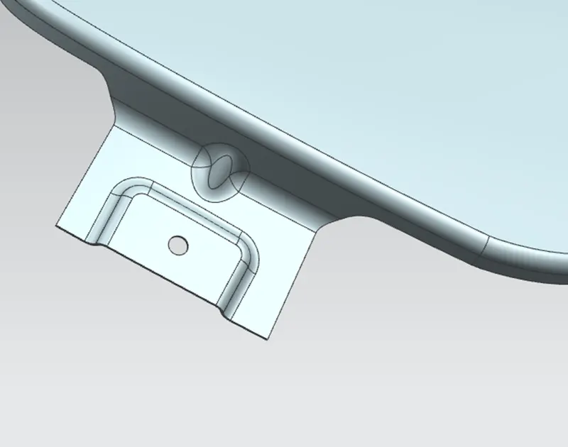
- First, I have started with law-extension of 35mm at the edge & at an angle of 75 degrees on the body mounting side.
- Then created a datum plane tangent to the surface created.
- And created a rectangle of 35 x 20mm & a circle of diameter 5 for screw mounting on the centre.
- Then using ‘projected curve’ projected those on the surface.
- Then used ‘emboss’ tool for creating the emboss by the sketch of 3.5mm distance & at an angle of 15 degrees.
- Then by using ‘trim sheet’ trimmed off the mounting diameter of 5mm.
- Then filleted the edges of the emboss using ‘edge blend’.
- And sewed the fender sheet & the extended flange to apply ‘dart’.
- Then used ‘dart’ to create a rib at the mid of the arc length of 5mm depth at the center of the arc length.
- Then blended the flange edge to 3mm using ‘edge blend’.
- Thus finished the body side mounting design.
Procedure followed for Fender baffle mounting design:
- For creating baffle mounting, created a first plane on the top surface of the mounting area.
- Then drawn a circle of diameter 5 offset to the edge of 6mm.
- Then projected the curve on the mounting surface using ‘projected curve’.
- And trimmed off the sketch using ‘trim sheet’.
- Then created a second plane on the top surface of the mounting area.
- Then drawn a circle of diameter 5 offset to the edge of 6mm.
- Then projected the curve on the mounting surface using ‘projected curve’.
- And trimmed off the sketch using ‘trim sheet’.
- Then created a third plane on the side surface of the mounting area.
- Then drawn a circle of diameter 5 offset to the edge of 6mm.
- Then projected the curve on the mounting surface using ‘projected curve’.
- And trimmed off the sketch using ‘trim sheet’.
- Then created a final plane on the bottom most surface of the mounting area.
- Then drawn a circle of diameter 5 offset to the edge of 6mm.
- Then projected the curve on the mounting surface using ‘projected curve’.
- And trimmed off the sketch using ‘trim sheet’.
- Thus finished the baffle mounting design.
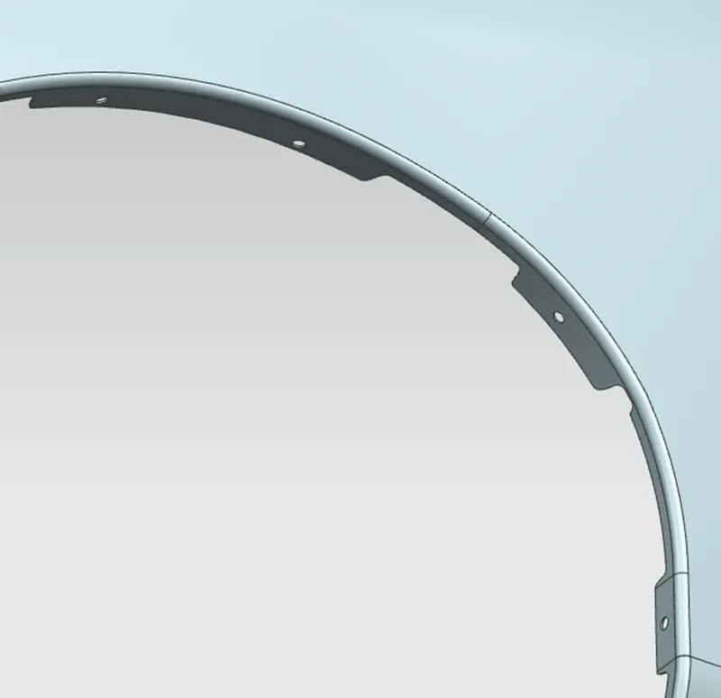
- Finally thickened the fender of 0.75mm inner side & finished the fender design.
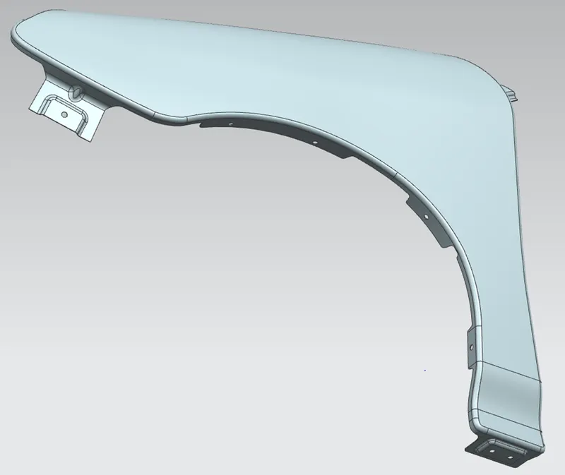
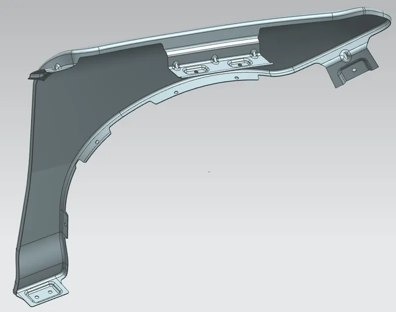
Finally, submitted the fender design.
Thanks,
Deepak kumar A S.