Fender Design
TITLE: FENDER DESIGN
OBJECTIVE :
The main objective of this project is to design a fender using a new age design software - NX - CAD
INTRODUCTION :
Fender is the US English term for part of an automobile (vehicle body of car) that frames the wheel well (the fender underside). Its primary purpose is to shield wheels and protect both passengers’ compartment and pedestrians from projection of water, mud and stones.
Fender is one of the styling components which is exposed to customer front which cannot be welded. Most of the assembling joining is done using fasteners, retainer clips and proper fitting.
Fenders are either made of steel or thermoplastics.
Types of Fenders:
- Full Bumper type
- Half Bumper type
Mounting Points of Fender:
- A-Pillar
- Bumper
- Sill
- Drip Area
- Splash Cover / Wheel Well
Design Data provided:
Master Section given:
Design Software used: CATIA V5
Design of Fender
The main objective here is to design Drip area, Bumper mounting region, Sill mount region, A-Pillar mount region and Splash cover or wheel well mount regions for the given fender skin or styling surface.
Design Considerations:
- Embosses are provided to increase strength.
- The corners of the flanges are smoothened to ease the producibility of part.
- Fillet of 2-3mm is provided to avoid sharp corners and edges.
- Cut outs are provided at certain regions in order to save material as possible.
- Uniform wall thickness of 0.75 mm is maintained.
DESIGN 0F DRIP AREA MOUNTING :
- It is the important mounting uni of the fender . it is connected with the engine compartment , therefore the lot of design constraints are to be followed while designing the fender
- While designing the drip area we have to initially leave 200-300 mm for cowl top
- For placing the headlamp we have to leave at least 150 mm at the front while designing the fender
- Cowl top part consists pf wiper motor and its instruments
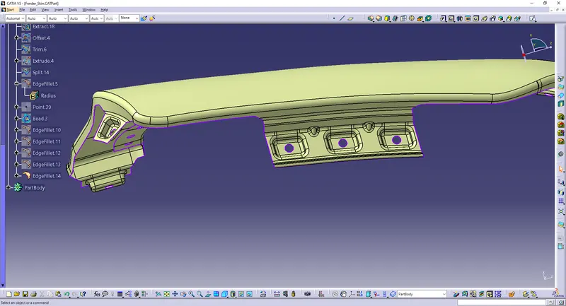
DRIP AREA
- Two darts are added on the longer side of the drip area in order to provide the stiffness and adds strength to the part . This helps the fender to not to vibrate and impact the forces outside of the fender during motion of the vehicle.
- Embossing are provided on the mounting to strengthen them during fastening
DESIGN OF SILL MOUNTING AREA :
Sill is the panel directly below the bottom of the door supporting the floor and may be used to combine the floor and the body . The bottom end of the fender is mounted on the sill body for reinforcement of the fender panel , thus the sill mounting position is designed with holes and emboss . M5 fasteners are used to fix the fenders on the sill body.
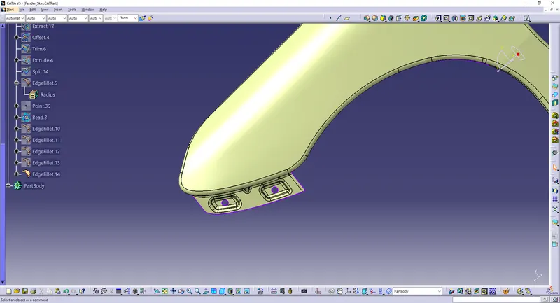
SILL MOUNTING
DESIGN OF BUMPER MOUNTING AREA :
Bumper mounting area is used to fix the plastic bumper to the fender with the help of the fasteners
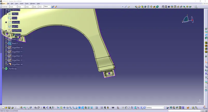
BUMPER MOUNTING
DESIGN OF A-PILLAR MOUNTING AREA :
The A -pillar is the structural pillar that combines the body to the roof . this make the sides of the windshield rest . front fenders are fastened to the A -pillar to form a robust structure .
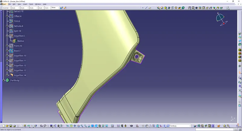
A-PILLAR MOUNTING
DESIGN OF BAFFLE MOUNTING AREA :
Baffle mounting or mudguard are clip fit type of mounting on the inner side of the fender arch over the Tyre . it protects the car engine compartment and pedestrians from causing injuries from chip out debris on the road when the car is in motion . they are mounted on the fender using a special type of locking clips which are made up of plastics .
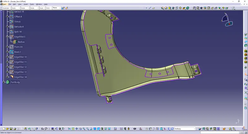
APPLYING OF THICKNESS TO THE SURFACE .
The thickness of 0.75 mm inward on the final sewed surface of the fender to the sheet metal parameters
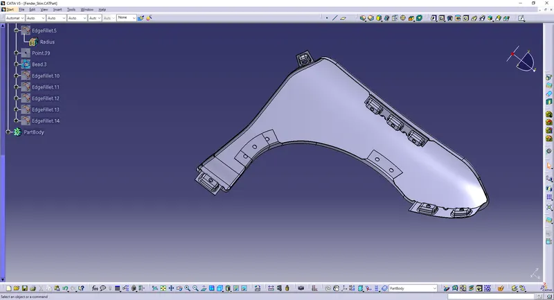
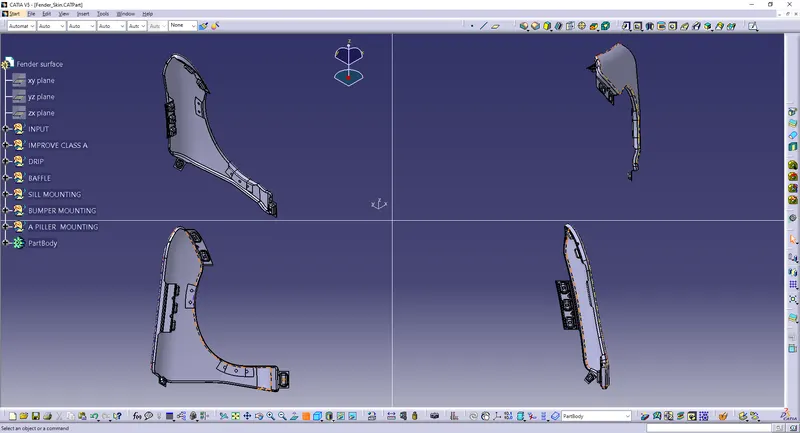
DIFFERENT VIEWS OF FENDER :
CONCLUSION :
Finally design of fender is done with the help of NX-CAD software by following the master section