Fender Design
FENDER DESIGN
AIM: To design a front fender of a car by following the given Drip area master section and Sill, Bumper, Baffle(Splash), and A-Pillar mount according to the Engineering standard.
Introduction:
Fender:
A fender is the part of an automobile, motorcycle, or other vehicle body that frames a wheel well. Its primary purpose is to prevent sand, mud, rocks, and liquids, from being thrown into the air by the rotating tire. Fenders are typically rigid and can be damaged by contact with the road surface.
Sticky materials, such as mud, may adhere to the smooth outer tire surface, while smooth loose objects, such as stones, can become temporarily embedded in the tread grooves as the tire rolls over the ground. These materials can be ejected from the surface of the tire at high velocity as the tire imparts kinetic energy to the attached objects. For a vehicle moving forward, the top of the tire is rotating upward and forward and can throw objects into the air at other vehicles or pedestrians in front of the vehicle.
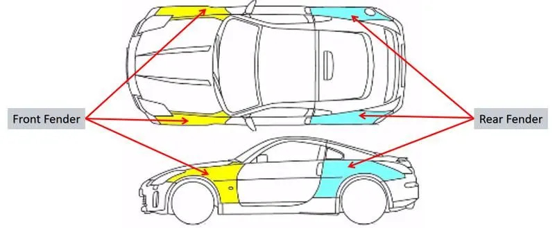
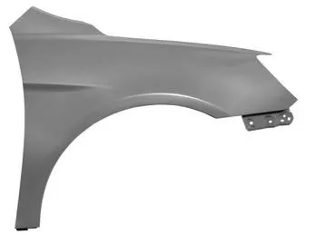
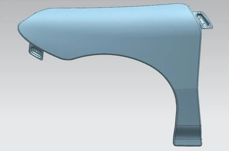
What is the purpose of a fender on a car?
The purpose of a fender is pretty simple. Its purpose is to cover the left and right side of the engine bay to protect it from side collisions and to keep mud, rocks, and other road debris from being thrown around by the tires. In other words, the fender is a housing for the wheels that keeps road debris contained. If nothing covers the wheels, all kinds of debris would be kicked up by the rotating tires and avoid hitting the pedestrians and the vehicles that come behind on the road.
Types of Fender:
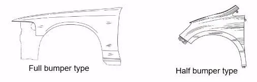
- Full-Bumper Type: Full-bumper type fenders were used in earlier models of vehicles. These types of fenders satisfy the purpose but also contribute the major amount of steel for just housing headlights along with bumper and hood the wheel wells. With this type of fender, there is a lot of waste in the blank size, and the industry pays for every inch of material used cost a lot.
- Half-Bumper Type: Half-bumper type fenders provide us with a solution that reduces enough consumption of steel by adding hard plastic without compromising the purpose of the fender. In this way, they can be economically manufactured by slightly increasing the blank size, we can produce two fenders on it. This helps in good cost-cutting and results in a reduction of the vehicle's weight.
Difference between a Fender and a Bumper?
A bumper is a component that is attached or integrated with the front and rear sides of a vehicle. The purpose of a bumper is to absorb the impact of minor collisions so that the car will be secured from these kinds of minor collisions. In the early days of the automobile, bumpers were a more distinct component that was noticeably separate from the rest of the car's body. However, as the automotive industry gets advanced, bumpers became more integrated with the rest of the car's body. The purpose of the modern bumper remains the same, but the bumpers on many vehicles (namely sedans and crossovers) are less visually noticeable than they were earlier.
Whereas, a fender is merely a housing or a cover for the wheels that prevent road debris from being thrown up by the rotating tires. However, fenders are also able to absorb impact from minor collisions. In this way, the fender can act as an extension of the bumper in terms of its ability to absorb the energy from a collision.
Design Considerations:
The design considerations that need to follow while designing the fender are the wheel arch calculation and the fender mounting points to the car body.
1. Wheel Arch:
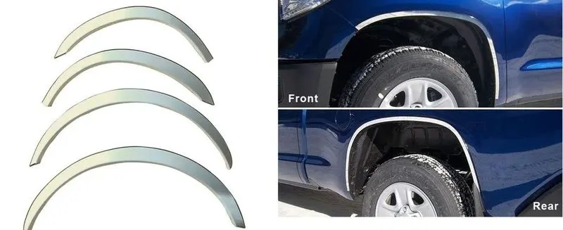
Wheel Arch is an arch-shaped cavity in the fender body, which houses a wheel. The main intention for the calculation of wheel arc radius is to position the wheel inside the fender body because during motion the car tires will tend to throw particles present on the road like sand, mudrocks, liquids, etc. into the air which may harm the pedestrians and cause problems. If the fender shin data doesn’t meet the required standard regulations, the fender class A surface is redesigned to meet the standards.
2. Mounting Points:
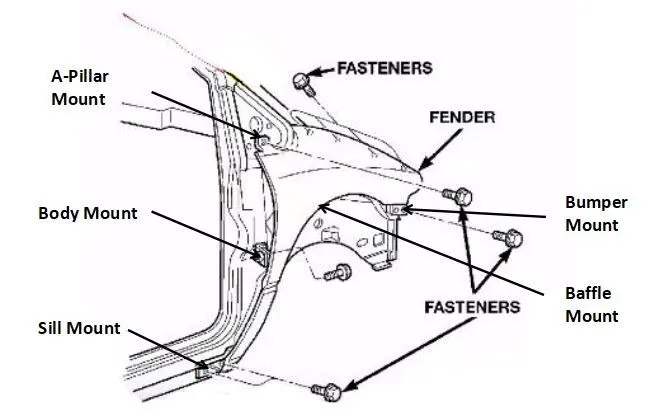
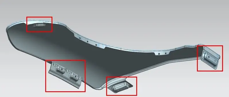
A car fender attaches to the front panels of the car with the support of mounting points. The front fender basically has five mounting positions with respect to the other components. All the mounting tab edges were rounded to avoid sharp edges for safety. The mounting positions are as follows:
Fender Design:
Data to be used:
Fender Thickness Information
Panel Thickness = 0.75mm
Mounting tabs Thickness = 0.75 mm
(As the fender skin data and mounting tabs are designed and manufactured as a single part)
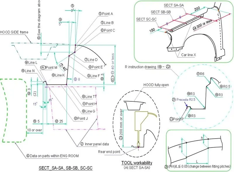
Master Section:
Drip Area Mounting:
- The drip area is the most important mounting tab in the fender, which attaches the fender to the engine compartment.
- The basic master section rule for the drip area mount is that it should be designed at least 150 mm away from the front end of the fender to have sufficient space for mounting headlamps housing and mostly 200 mm away from the rear end of the fender, to have sufficient space for the cowl mount to carry wiper equipment.
- The length of the drip area depends on the length of the fender and the mounting tab angles are designed in order for tool workability and to avoid the direct view of engine compartment for the pedestrian.
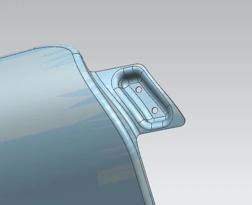
A-Pillar Mounting:
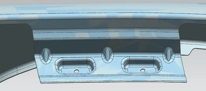
- This mounting position is created for attaching the fender to A Pillar of the vehicle.
- The mounting has to be created by taking the reference from the A-pillar and BIW of the vehicle.
- Enough clearance should be given for the tool workability and easy mounting for the wiper equipment.
Sill Mounting:
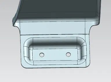
- Sill mounting is created for attaching the fender to the bottom portion or the sill.
- The mounting points are joined by the fasteners and it is either covered by the front door or by the fender surface itself.
Bumper Mounting:
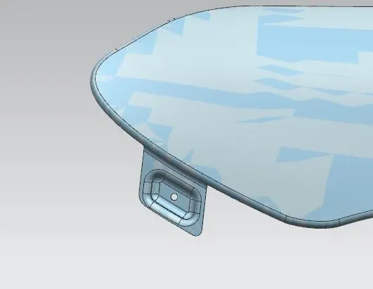
- This mounting point is created for attaching the fender to the front bumper.
- It should have enough strength to hold the bumper sides steadily.
- The mounting tabs are fixed by fasteners to the bumper inwardly and it is covered by the bumper surface.
Baffle Mounting:
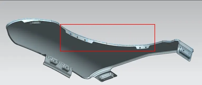
- These mounting points are created for attaching plastic components i.e either the baffle or the wheel arch housing which prevents chipping from both inside and outside of the engine compartment.
Manufacturing process involved in Hood Assembly:
Deep Drawing:
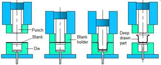
Deep drawing is a manufacturing process that is widely used in the formation of flat sheet metal into cup-like or box-like structures and even more complex contours. However, as complexity increases, manufacturing problems increase rapidly. It is better to design the shape of a deep drawing to be as simple as possible. Automobile parts, such as panels and gas tanks, are among a few of the items manufactured by sheet metal deep drawing.
Deep drawing is a sheet metal forming process with a punch and die that involves intricate material flow and force distributions. The punch and die setup is most similar to a sheet metal cutting operation, such as punching or blanking. Two main factors will cause the punch in a deep drawing to draw the metal into the die cavity, rather than shearing it. One major factor in the deep drawing is the die corner radius and the punch corner radius. When cutting sheet metal, the punch and die edges do not have a radius. Sharp corners on the punch and die cause it to cut. The force distribution will be altered by a radius on an edge, causing the metal to flow across the radius and into the die cavity. The amount of clearance is another important component that contributes to the punch drawing the sheet metal rather than cutting it. In the cutting process, clearance is typically between 3% and 8% of the thickness of the sheet metal. Deep drawing manufacturing often has clearance values between 107% and 115% of sheet thickness, which is larger than the thickness of the sheet.
Embossing:
Sheet metal embossing is a stamping process for producing raised or sunken designs or relief in sheet metal. This process can be made through matched male and female roller dies, or by passing a sheet or a strip of metal between rolls of the desired pattern. It is often combined with Foil Stamping to create a shiny, 3D effect. The metal sheet embossing operation is commonly accomplished with a combination of heat and pressure on the sheet metal, depending on the types of embossing is required. Theoretically, with any of these procedures, the metal thickness is changed in its composition.
Blanking & Piercing:
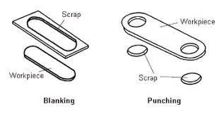
Blanking and piercing are shearing processes in which a punch and die are used to produce parts from sheet metal. Blanking produces the outside features of the component, while piercing produces internal holes or shapes.
Conclusion:
The front fender is designed according to the given master section with the help of the given class A surface as per the OEM Standards and the manufacturing process has been explained.