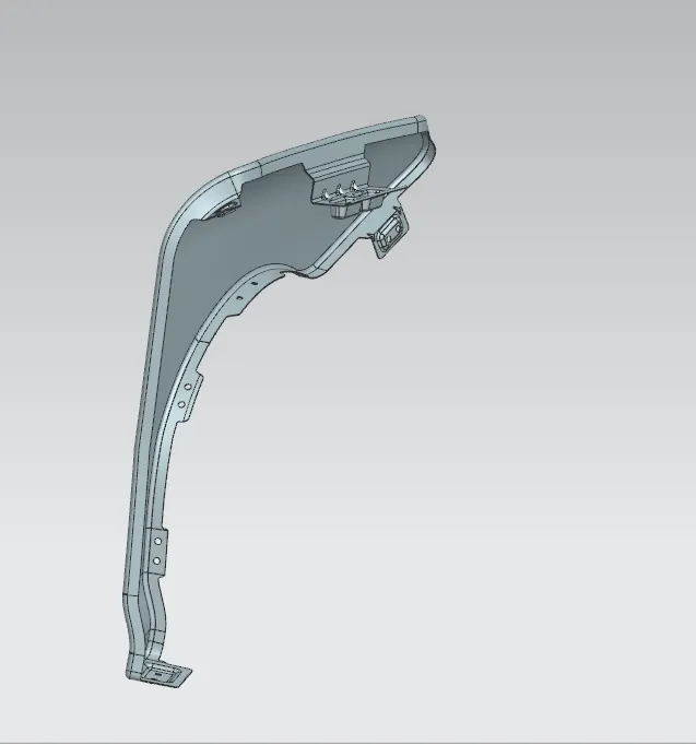
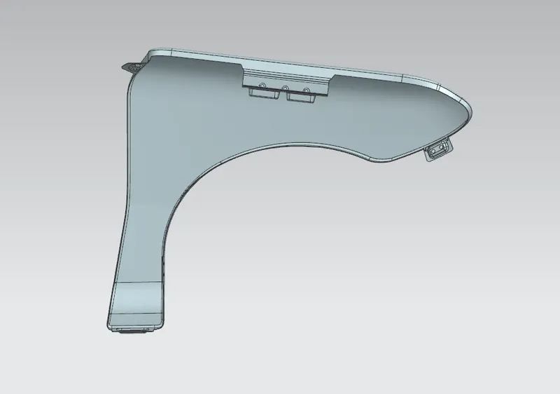
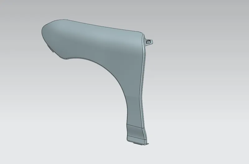
Fender Design
FENDER DESIGN
Aim : -The primary goal of this project is to create a fender using a cutting-edge design software called NX CAD.
Introduction -
The portion of an automobile, motorbike, or other vehicle body that frames a wheel well is referred to as a fender in American English (the fender underside). The major function of this device is to keep sand, dirt, gravel, liquids, and other road spray from being flung into the air by the revolving tyre. Fenders are normally stiff and can be damaged by road surface contact.
Sticky materials, like mud, may attach to the smooth outer tyre surface, while smooth loose items, like stones, may become momentarily lodged in the tread grooves when the tyre rolls over the ground. As the tyre transmits kinetic energy to the connected items, these materials can be expelled off the surface of the tyre at high velocity.
When a vehicle moves ahead, the top of the tyre rotates upward and forward, throwing debris into the air and potentially hitting other cars or pedestrians in front of the vehicle.
The fender is known as the wing in British English. (This might apply to either the front or back fenders. However, in current unibody automobiles, rear fenders are sometimes referred to as quarter panels.) In the United Kingdom, the equivalent component of a bicycle or motorcycle, or the "cycle wing" style of wing fitted to vintage cars, or over tyres on lorries that is not integral with the bodywork, is known as a mudguard, as it protects other road users - and, in the case of a bicycle or motorcycle, the rider - from mud and spray.
There are two types of Fender
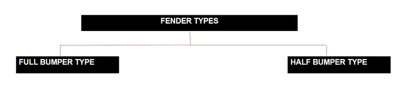
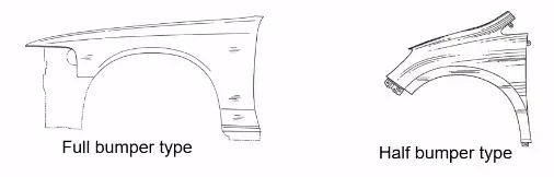
FULL BUMPER DESIGN
Full bumper fenders are no longer utilised because larger blanks are required to create the part and waste material is generated during the production process.
HALF BUMPER DESIGN
Half bumper fenders are employed because they generate two fenders at the same time by slightly increasing the raw sheet. and bumper fenders are commonly used to minimise weight and cost.
FRONT FENDER MANUFACTURING:
- Process planning of automobile panels is used to determine the number of operations, the tasks inside each operation, and the content of each work. This study presents an automated reasoning technique based on expert expertise and physical rules.
- Calculate the blank size.
- Trimming job: The trimming task is divided into two sections.
- Restriking is required when surfaces distort due to springback after drawing and trimming, or when the accuracy demand is high because one surface overlaps another surface of another panel during assembly. Restriking is necessary to counteract the springback of sheet metal.
- Piercing task: A piercing task is required for each hole feature. Based on their purposes during assembly, hole characteristics are classed as basic holes, lock holes, and expand holes. A basic hole is used to locate the panel, and a lock hole is used to lock panels.
- Burying is the process of removing sharp edges and damaging burs from a component.
FENDER WHEEL ARCH :
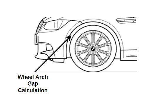
- Fender wheel arch has some basic standards, for example, if you see the car from the front, if you notice the wheel outside the fender, it creates more chipping and causes a lot of harm to pedestrians as well as the automobile.
- To ensure pedestrian safety, we must position the tyre wheel within the fender.
- The European standard requires a 5mm space between the wheel and the fender's outermost surface.
- This criterion varies from nation to country depending on road conditions.
ASSEMBLY:
There are two kinds of assemblies, which are
Bottom-up assembly
Top-down assembly
Bottom-up assembly: Bottom-up assembly is the recommended method for developing assembly models. The components in this sort of assembly are developed in a part design work bench (As nx cad part) file. Product structure tools are used to create parts in the assembly design workbench. After adding each component, constraints are applied to appropriately arrange them in 3D space in relation to the other components. This construction is suitable for big assemblies with complicated individual components.
Top-down assembly:Components are developed inside the assembly design workbench in the top assembly design technique. As a result, there is no need to generate separate part files for each component. This design technique differs significantly from the bottom-up design approach. Generate the product file first, and then create all the components one by one. Even though the pieces are produced in the product file, they are stored and accessed independently as required. Construction and assembly take place concurrently here.
FENDER MOUNTING REGIONS:
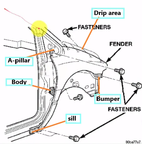
There are 5 mounting regions on the fender , they are
- A- pillar mounting
- Body mounting
- Sill mounting
- Bumper mounting
- Drip mounting
DESIGN METHODOLOGY :
GIVEN DATA :
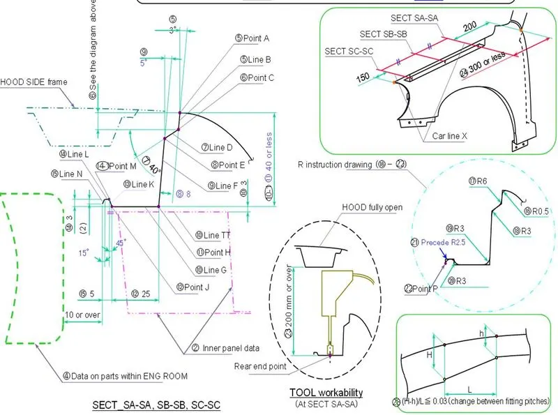
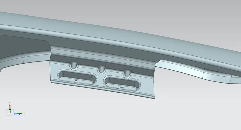
DRIP AREA MOUNTING DESIGN:
The drip area is designed with a 150mm clearance from the front-end for headlamp fittings and a 200mm clearance from the rear-end for the wiper motor assembly (Cowl top area)
To eliminate the spring-back effect, the drip area is kept at a depth of less than 60mm.
Ribs are installed at the fender drip region to boost strength.
SILL MOUNTING AREA DESIGN:
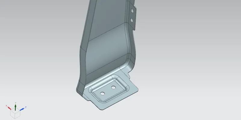
Sill is the panel right under the bottom of the door that supports the floor and can be utilised to connect the floor and the body. To reinforce the fender panel, the bottom end of the fender is mounted on the sill body, thus the sill mounting location is built with holes and emboss, and M5 fasteners are used to secure the fenders to the sill body.
BUMPER MOUNTING AREA DESIGN:
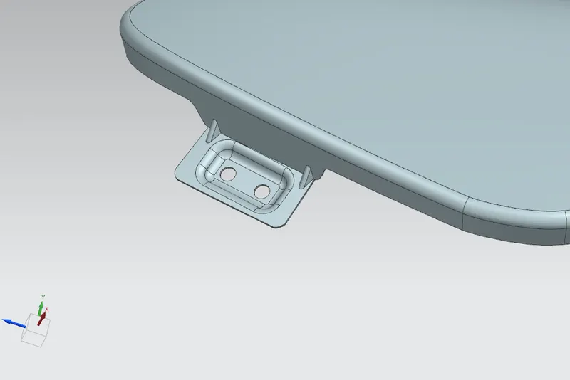
The bumper mounting area is utilised to secure the plastic bumper to the fender using screws.
A-PILLAR MOUNTING AREA DESIGN:
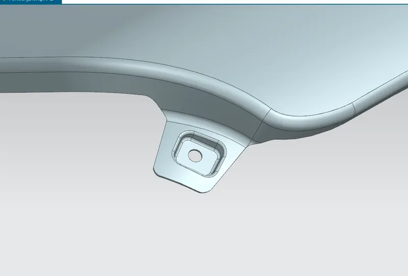
The structural pillar that connects the body to the roof is the A-pillar. This allows the sides of the windscreen to rest. Front fenders are secured to the A-pillar to provide a strong framework.
BAFFLE MOUNTING AREA DESIGN:
Baffle mounting or mudguards are clip-on mountings that go on the inside side of the fender arch above the tyre. When the automobile is in motion, it protects the engine compartment and pedestrians from being injured by chip out objects on the road. They are attached to the fender with an unique sort of locking clip made of plastic.
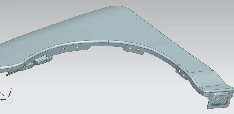
The thickness of 0.75mm inward on the final sewed surface of the fender to the sheet metal parameters.
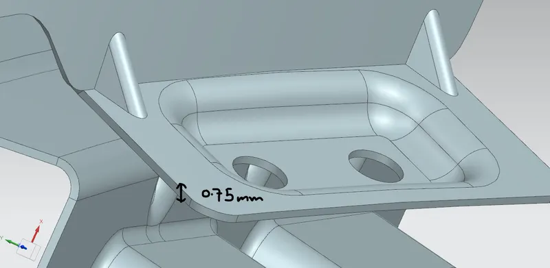
Final model